EPSON Stylus COLOR 440, 640, and 740 Chapter 4 Disassembly and Assembly
105
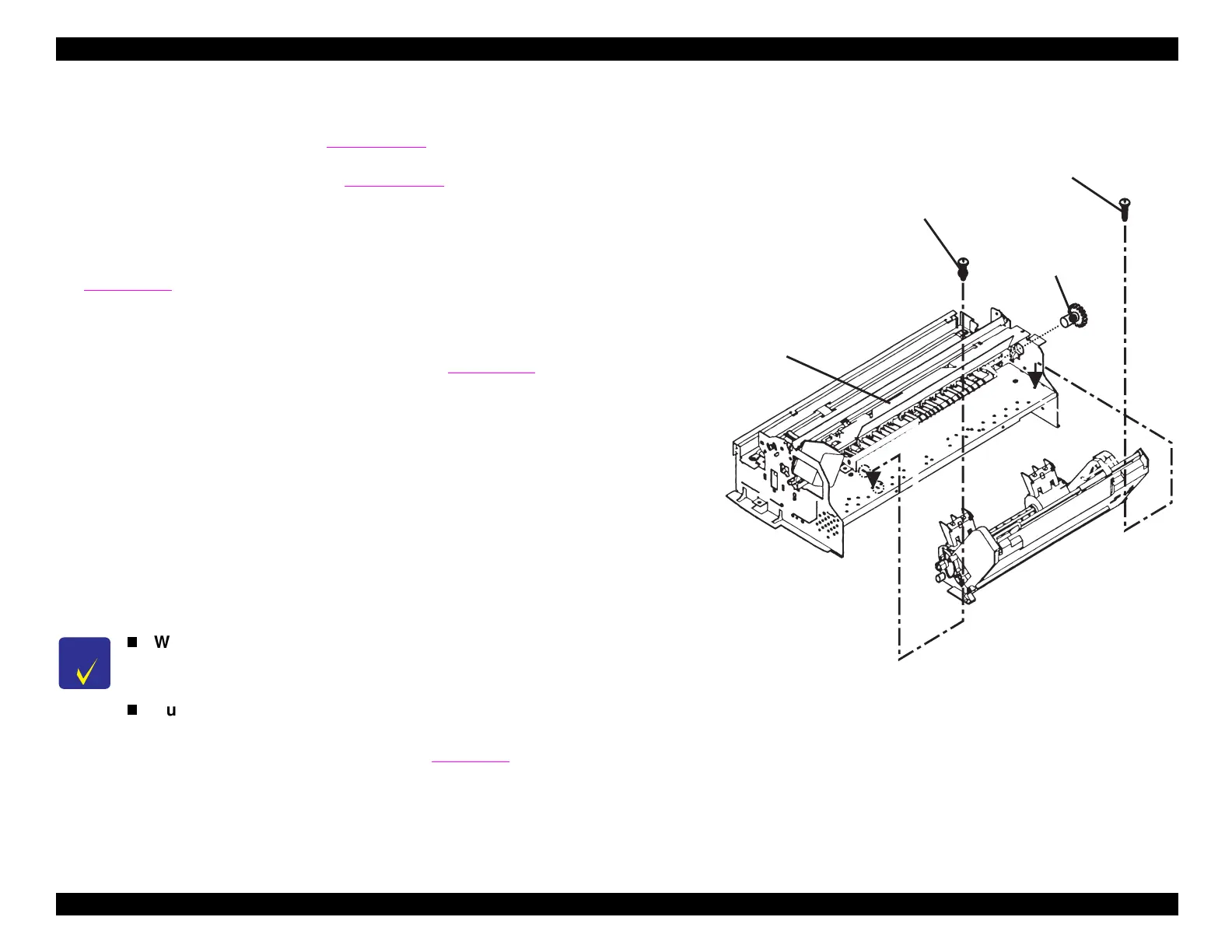
4.2.4.6 Removing the ASF Assembly
1. Remove the housin
.
Refer to Section 4.2.1.
2. Remove the board assembl
see Section 4.2.2
. Then disconnect
the ASF sensor from the main board
CN11 on the St
lus COLOR
440 and 640; CN6 on the St
lus COLOR 740
.
3. Remove the 3 screws
No.1
from the PH cable
uide plate.
See
Fi
ure 4-20.
Slide the plate toward the left side of the printer to
unhook it from the frame. Without detachin
the cables or kinkin
them, set the
uide plate to the side of the printer mechanism.
4. Remove
ear 34 from the ASF assembl
.
See Fi
ure 4-15.
To
remove the
ear, turn it so that the two black hooks holdin
it on the
inner shaft become visible. Gentl
pr
the hooks outward from the
shaft with tweezers while pullin
on the
ear to remove it.
5. Remove the PF motor cable from the hook on the side of the ASF
assembl
.
6. Remove the 2 screws that hold the ASF in place
1 No.7 screw with
a washer and 1 CR shaft installation screw
. Remove the ASF
assembl
b
liftin
it upward.
Figure 4-15. Removing the ASF Assembly
CHECK
POINT
When installing the ASF assembly, make sure that the
ASF assembly is properly seated on the frame,
without any space between the ASF and the frame.
During reassembly, be sure to route the ASF sensor
cable through the right cable hook and the right cable
holder, as seen from the rear (see
Fi
ure 4-3
).
Screw w ith a W asher (N o.7)
G ear 34
C R S haft Installation Scre
Printhead C able G uide P late
 Loading...


