EPSON Stylus COLOR 440, 640, and 740 Chapter 2 Operating Principles
44
Head Cleaning Operations
The printer performs a variet
of tasks to keep the printhead clean and
to keep ink from dr
in
out on the printhead’s surface. These tasks
include:
Rubbing and Wiping
Rubbin
and wipin
are performed prior to suctionin
to eliminate dust
and dirt on the printhead. This helps maintain normal ink e
ection and
ensures that a firm seal can be obtained when the printhead is capped
durin
suctionin
.
Rubbin
and wipin
occur when the printhead passes over the cleanin
blade, which can be extended into the path of the printhead or
withdrawn out of its wa
. To learn how this works, see “Pump
Mechanism” on pa
e45.
The cleanin
blade is composed of two materials: felt on the left side
and rubber on the ri
ht. When the carria
e moves ri
ht to left, the
printhead
rubs
a
ainst the rubber half of the blade. When the carria
e
moves left to ri
ht, the printhead
wipes
a
ainst the felt half. A small
amount of ink is sent to the nozzle surface before wipin
to make
adherin
ob
ects come off easil
.
Discharging
Dischar
in
is the electronicall
controlled e
ection of ink from the
printhead. Unlike suctionin
, which uses an external pump, dischar
in
uses the printhead’s own PZTs to perform the operation. Dischar
in
eliminates the viscous ink that forms when ink near the printhead
nozzles starts dr
in
out.
Suctioning
Suctionin
takes place when the printer uses the ink pump to suction
ink awa
from the nozzles. This eliminates trapped air bubbles and
prevents ink from remainin
near the nozzles and dr
in
out.
The printer performs suctionin
at three different power levels. Durin
hi
h-power suctionin
, the printhead is full
capped and the bleed valve
remains closed. This
ives rise to maximum suction. The printer then
switches to medium-power suctionin
, a sensitive operation performed
with the bleed valve open. This eliminates air bubbles formed in the
printhead cavit
durin
hi
h-power suctionin
. Finall
, with the bleed
valve still open but the pump motor runnin
at a lower speed, the printer
performs low-power suctionin
. This vacuums awa
an
ink that
remains on the nozzle plate and in the ink cap followin
other cleanin
procedures.
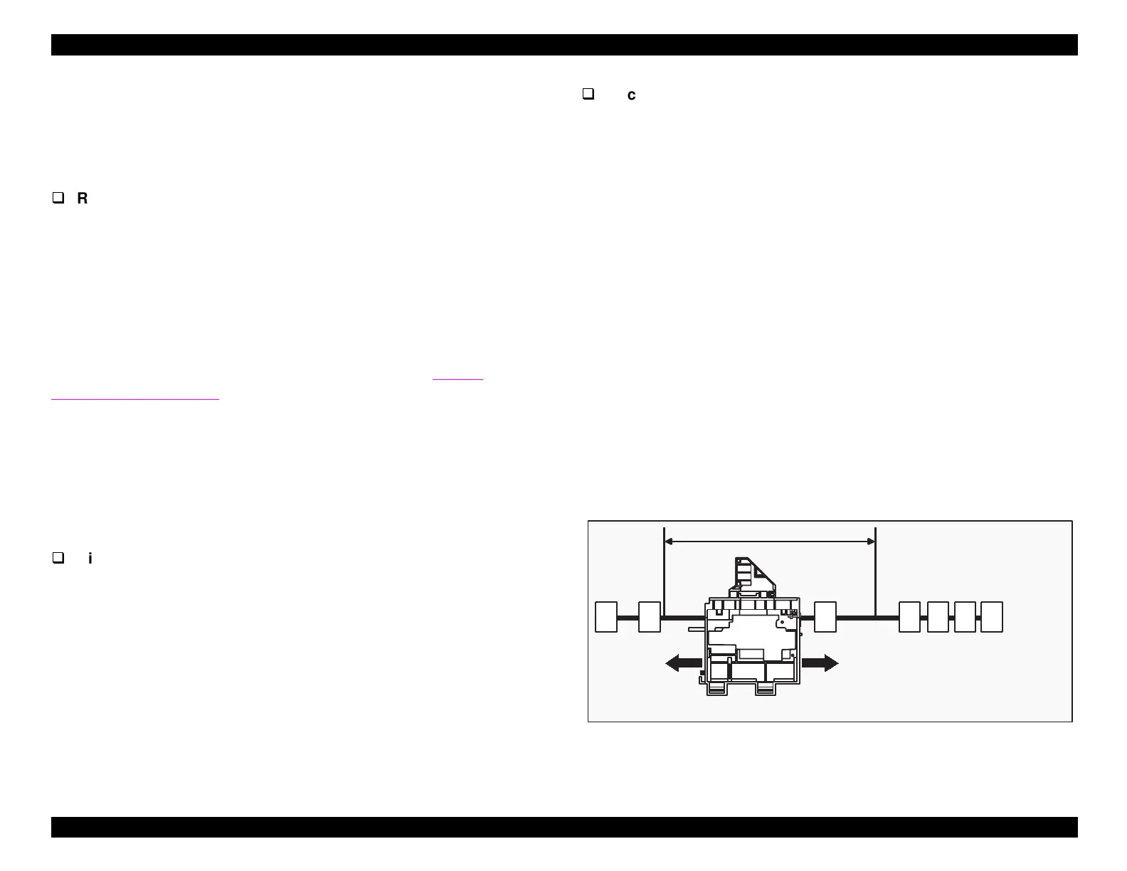
The fi
ure below shows where the carria
e is positioned durin
the
various head cleanin
operations.
Figure 2-11. Carriage Positioning
ABCDE
FG
Printable Area
A: Medium- and low-power suctioning position
B: High-power suctioning position (home position)
C: Discharging position (right)
D: Wiping/rubbing position
E: Cartridge replacement position
F: Discharging position (left)
G: ASF drive position
 Loading...


