EPSON Stylus COLOR 440, 640, and 740 Chapter 1 Product Description
22
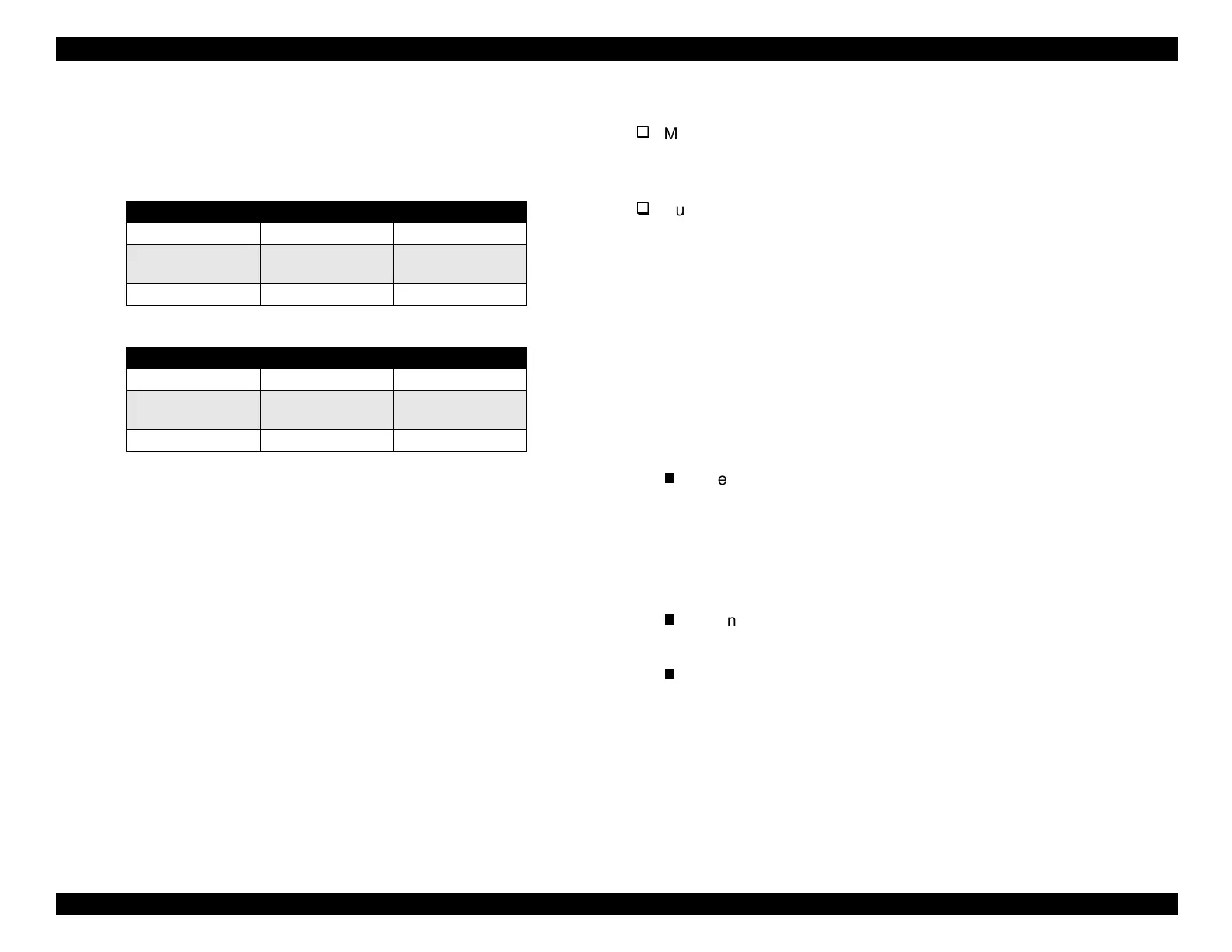
The followin
tables show t
pical input and output si
nal levels for the
interface
IEEE-1284 level 1 device
. Si
nal levels are based on TTL
standards.
Table 1-15. Typical Output Signal Characteristics
Table 1-16. Typical Input Signal Characteristics
NOTE: The input and output signals are active-high; the logic level is
considered HIGH at 3.0 volts or more and LOW at 2.0 V or
less. The receiver shall provide an impedance equivalent to
7.5K ohm to ground.
1.3.2.1 Host Data Transfer Timeout Prevention
Generall
, hosts abandon data transfer to peripherals when a peripheral
is BUSY continuousl
for dozens of seconds. To prevent this kind of
time-out, the printer receives data ver
slowl
, several b
tes per minute,
even if it is bus
. This slowdown starts when the remainder of the input
buffer drops under several hundred b
tes. In addition, the printer is
BUSY continuousl
when the input buffer is full.
1.3.2.2 Interface Selection
Manual Selection:
One of two interfaces can be selected throu
h the default settin
mode.
Automatic Selection
St
lus COLOR 740 onl
:
Automatic interface selection is enabled in the default settin
mode.
In automatic interface selection mode, the printer is initialized to the
idle state when it is powered on. The printer scans the interfaces to
determine which interface receives data first, then selects that
interface for further data transmission. When the host stops data
transfer and the printer is in stand-b
for several seconds, the
printer returns to the idle state. The process is repeated each time
the printer is powered on.
The followin
notes explain how the selection of one interface affects
the condition of other interfaces:
When an interface other than the parallel interface is selected,
the parallel interface
oes into the BUSY state. The LH si
nal is
set to LOW, blockin
the power suppl
and preventin
a
response from the 1284 Active si
nal. This makes it necessar
for the host, which re
uires reverse transfer of data, to check the
LH state.
When an interface other than the serial interface is selected, the
serial interface sets the DTR si
nal MARK.
When the printer is initialized or returned to the idle state, the
parallel interface
oes into the read
state. The serial interface
sets the DTR si
nal SPACE
LOW
and resets the off-line bit of
the Main Status Re
ister
MNSTS
to an optional interface.
Parameters Minimum Maximum
Voltage -0.5 V 5.5 V
Current 0.32 mA
when V
out
= 2.4 V
12 mA
when V
out
= 0.4 V
Capacitance — 50 pF
Parameters Minimum Maximum
Voltage 0.8 V 2.0 V
Current 0.32 mA
when V
in
= 2.0 V
12 mA
when V
in
= 0.8 V
Capacitance — 50 pF
 Loading...


