EPSON Stylus COLOR 440, 640, and 740 Chapter 2 Operating Principles
36
2.1.1 Printhead
The printhead of the St
lus COLOR 440, 640, and 740 combines the
black and CMY
C
an, Ma
enta, Yellow
heads in one unit. As shown
below, the nozzle confi
urations are different for each model:
St
lus COLOR 440:
Black Nozzle: 64 nozzles
90 dpi x 2 rows sta
ered
CMY Nozzle: 21 nozzles per color
90 dpi x 1 row
St
lus COLOR 640:
Black Nozzle: 64 nozzles
90 dpi x 2 rows sta
ered
CMY Nozzle: 32 nozzles per color
90 dpi x 1 row
St
lus COLOR 740:
Black Nozzle: 144 nozzles
120 dpi x 3 rows sta
ered
CMY Nozzle: 48 nozzles per color
120 dpi x 1 row
The St
lus COLOR 640 and 740 print at the hi
hest resolution
720 x
1440 dpi
, while the St
lus Color 440 prints at 720 x 720 dpi.
The printhead uses an on-demand MACH-t
pe ink deliver
s
stem.
Refer to Fi
ure 1-1, Fi
ure 1-2, and Fi
ure 1-3 for the nozzle
confi
uration. In order to correct manufacturin
variations in the piezo
elements used for e
ectin
ink from the nozzles,
ou must input the
head volta
e ID to the printer whenever
ou replace the printhead, main
board, or printer mechanism. The head volta
e ID is marked on the
side of the printhead, and is stored in the EEPROM on the printer’s
main board. You can input the ID to the printer b
usin
the ad
ustment
pro
ram described in “Usin
the Ad
ustment Pro
ram” in Chapter 5,
Adjustments
.
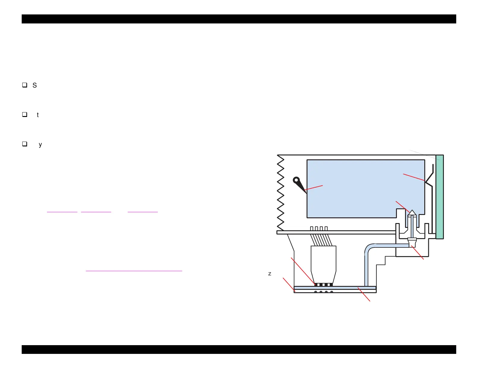
Printing Process
In Fi
ure 2-2, the ink cartrid
e sensor detects the presence of the ink
cartrid
e; note that the sensor’s position differs between models. After
ink flows out of the cartrid
e throu
h the needle, it passes throu
h a
filter. The filter prevents dust or dirt from clo
in
the ink nozzles and
causin
missin
dots or ink deflection. The ink cavit
then stores the ink
until it is read
to be dischar
ed. This is accomplished b
piezo electric
elements
PZTs
. In response to si
nals from the driver on the main
board, the PZTs compress the top of the ink cavit
, causin
ink to e
ect
throu
h the nozzle plate on the bottom of the printhead.
Figure 2-2. Printhead Sectional Drawing
Ink C artridge S ensor
(Stylus C O LO R 440,640)
Ink C artridge S ensor
(Stylus C O LO R 740)
(In k C a rtrid g e )
N o z z le S e le c to r B o a rd
N eedle
ozzle P late
PZT
In k C a v ity
F ilte r
 Loading...


