EPSON Stylus COLOR 440, 640, and 740 Chapter 2 Operating Principles
45
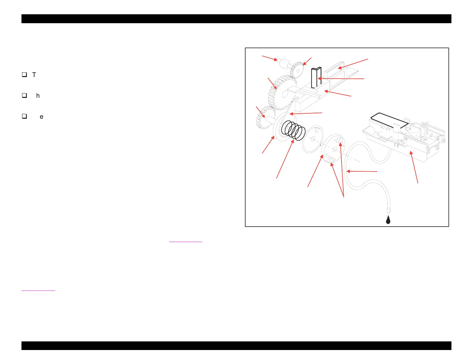
Pump Mechanism
The pump mechanism, shown in Fi
ure 2-12, actuall
performs three
different functions:
The pump itself removes ink from the ink cartrid
e, as part of the
head cleanin
operation.
The cleanin
blade removes dust and dirt from the printhead, as
part of the head cleanin
operation.
The carria
e lock retains the carria
e in its home position, to ensure
that the printhead remains capped when the printer is not in use.
The cleanin
blade and the carria
e lock are mounted on the same
slider unit, and therefore extend or retract in tandem. The slider’s
motion is controlled b
the slider lever, which is held a
ainst the clutch
plate b
a compression sprin
. Because the slider lever is operated b
friction instead of
ears, the rest of the pump mechanism can continue
to turn even when the slider unit is full
extended or retracted.
However, this also means that even a minor obstruction can cause the
slider to stick.
The pump itself uses peristaltic compression. Rollers attached to the
pump drive wheel create a vacuum in the ink drain tube b
s
ueezin
the tube alon
its len
th and forcin
the ink to travel throu
h it. This is
shown in Fi
ure 2-12 at ri
ht, and schematicall
in Fi
ure 2-13 on the
followin
pa
e.
As mentioned above, the PF motor is the power source for both the
paper feed mechanism and the pump mechanism. The PF motor
powers the pump mechanism throu
h the e
ect roller shaft, as shown in
Fi
ure 2-10 and Fi
ure 2-12 at ri
ht.
Figure 2-12. Pump Mechanism
Eject R oller
Shaft
Gear A
Gear B
Gear C
C lutch plate
Com pression
spring
Rollers
Pum p drive
w heel
In k d ra in
tube
C apping unit
Slider lever
Slider
C leaning blade
C a rria g e lo c k
 Loading...


