EPSON Stylus COLOR 440, 640, and 740 Chapter 2 Operating Principles
46
Althou
h econom
of desi
n results from the pump mechanism and the
paper feed mechanism sharin
the same motor, it is not desirable for
the pump to be runnin
ever
time the printer feeds paper. To
overcome this problem, the operations of paper feedin
and pumpin
are kept separate b
the PF motor’s direction of rotation. Since the
printer feeds paper in one direction onl
, the other direction is reserved
for runnin
the pump.
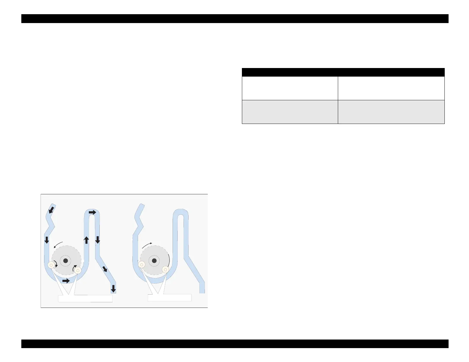
Here’s how that works: Slots in the pump’s drive wheel permit two
rollers to move radiall
inward or outward, dependin
on the wheel’s
direction of rotation. As shown in Fi
ure 2-13, when the pump turns
counterclockwise
as viewed from the left side of the printer
, the rollers
are forced outward to compress a
ainst the ink drain tube. This is
caused b
the an
le of the slots and friction between the rollers and the
drain tube. In this position, pumpin
takes place. When the pump
turns clockwise
the direction of paper feedin
, the rollers relax and
move inward, and no pumpin
occurs.
Figure 2-13. Pump Rotation
The table below summarizes the relationship between the PF motor’s
direction of rotation and the pump mechanism’s operation.
Table 2-7.
PF Motor and Pump Mechanism Functions
For the pump to drain ink awa
from the cartrid
e, not onl
must the
pump be runnin
, but the printhead must be firml
seated on the
printhead cappin
mechanism with the air bleed valve closed. The
followin
section explains the operation of the cappin
mechanism.
Tube com pressed
Tube released
C W R o ta tio n
CCW Rotation
PF Motor Rotation Pump Mechanism Functions
Clockwise (CW) Pump operates
Head cleaner extends
Carriage lock extends
Counterclockwise (CCW) Pump does not operate
Head cleaner retracts
Carriage lock retracts
 Loading...


