EPSON Stylus COLOR 440, 640, and 740 Chapter 4 Disassembly and Assembly
111
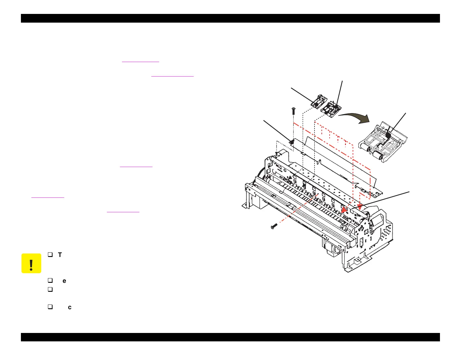
4.2.4.8 Removing the Paper Feed and Paper Eject Roller
Assemblies
1. Remove the housin
.
Refer to Section 4.2.1.
2. Remove the carria
e assembl
.
Refer to Section 4.2.4.7.
3. Remove the 3 screws
No.1
that hold the cable
uide plate in place,
and remove the cable
uide plate. See Fi
ure 4-20.
4. Remove the 6 pinch rollers, releasin
their sprin
s from the hooks in
the top frame.
5. Take out 2 screws
No.1
and remove the paper e
ect frame
to
ether with its star wheels
not shown
.
6. Remove the platen b
first liftin
its left end, then liftin
up the ri
ht.
Then pull it out to the left. See Fi
ure 4-21.
7. Remove the pump drive shaft, b
pullin
inward
then
up
on the
lockin
tabs located on the ri
ht and left ends of the shaft. See
Fi
ure 4-21.
8. Remove the PF roller
see Fi
ure 4-22
b
pullin
out on the lockin
tab located on the left side of the PF roller. Then rotate the tab so
that the other tabs ali
n with the notches in the frame. Slide the PF
roller assembl
to the ri
ht and pull it out.
Figure 4-20. Removing the Paper Guide Assembly
CAUTION
The PE sensor lever fits through the right-most pinch
roller assembly. Be careful not to damage the lever
when removing or installing the pinch roller.
Be careful not to damage the hooks on the platen.
Be careful not to scratch the PF roller, since its
surface is specially coated to improve paper feeding.
Be careful not to damage the combination gears.
C able G uide P late
(N o.1)
Pinch R oller
Assem bly (6)
Left Paper G uide
Torsion S pring
117.6
(N o.1)
Top Fram e
 Loading...


