EPSON Stylus COLOR 440, 640, and 740 Chapter 5 Adjustments
133
5.2.2.9 Head Angle Adjustment
The head an
le ad
ustment corrects for manufacturin
variations in the
shape of the carria
e and the printhead. If this ad
ustment is not
performed, bandin
ma
occur in the printed output. You must perform
this ad
ustment in the followin
cases:
After replacin
the printhead
After replacin
the carria
e unit
If
ou have chan
ed the an
le of the ad
ustment lever
In order to perform the ad
ustment,
ou must first print the head an
le
check pattern as described below. Then use the ad
ustment lever,
which is located on the ri
ht side of the carria
e unit, to set the
printhead an
le accordin
l
.
1.
Remove the upper housin
from the main unit.
See Section 4.2.1.
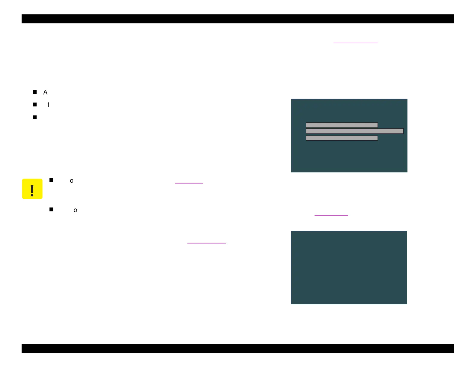
NOTE: If you prefer, you can perform this adjustment without
removing the upper case. When you need to access
the carriage unit, select “Move the carriage to the head
angular adjustment position” on the screen shown in
Figure 5-26.
2.
Enter the main menu
see Section 5.2.2.3
. Then select
Adjustment
.
3.
In the ad
ustment menu, select
Head Angular Adjustment
. The
followin
screen appears.
Figure 5-26. Head Angle Adjustment Menu
4.
Select
Head Angular Adjustment Pattern
and press Enter. The
followin
screen appears and the printer prints the head an
le
ad
ustment pattern
Fi
ure 5-28 on the next pa
e
.
Figure 5-27. Printing the Head Angle Adjustment Pattern
CAUTION
Before makin
this ad
ustment, refer to Table 5-1 and
make an
other re
uired ad
ustments, followin
the order
listed in the table.
Use onl
hi
h-
ualit
720 dpi
ink
et paper for printin
the check pattern because of the hi
h de
ree of precision
re
uired.
M S-D O S Prom pt-S C 640
H ead Angular A djustm ent
Esc: P revious
H ead Angular A djustm ent pattern
E n te r: O K
M ove the carriage to the head angular adjustm ent position.
R eturn the carriage to the hom e position.
M S-D O S P rom pt-S C640
The H ead A ngular Adjustm ent pattern is now printing.
 Loading...


