EPSON Stylus COLOR 440, 640, and 740 Chapter 5 Adjustments
134
Figure 5-28. Sample of Head Angle Adjustment Pattern
5.
Loosen the printhead securin
screw that secures the printhead to
the carria
e.
You don
'
t need to remove it completel
.
Figure 5-29. Screw Location
6.
Look at the overlappin
area between the black lines and the
ma
enta lines in the check pattern. Move the ad
ustin
lever so that
the black and ma
enta lines are evenl
spaced, as shown in Fi
ure
5-30 below.
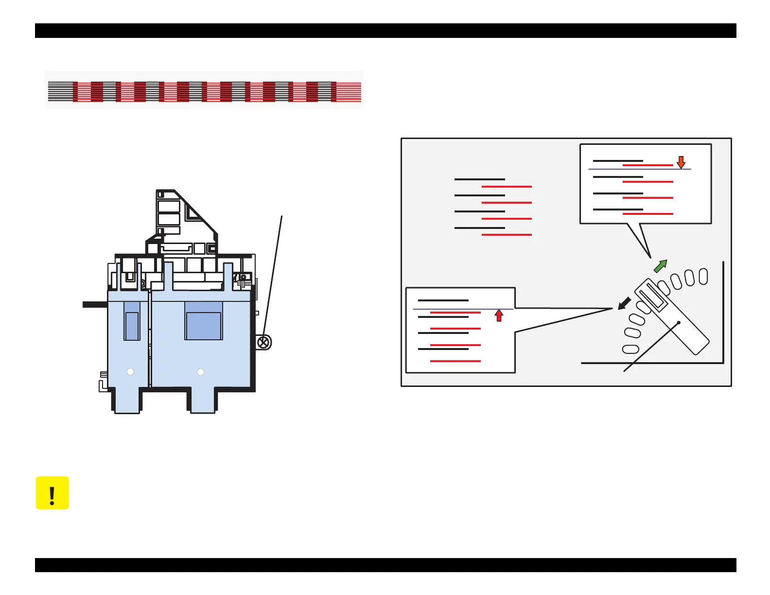
Figure 5-30.
Lever Operation and Corresponding Change in Pattern
NOTE: Because this adjustment requires a high degree of
precision, you may wish to use a magnifying glass or
an eye-loupe when viewing the check pattern.
CAUTION
Be sure to loosen this screw. Otherwise, the printhead
angle will not change even if you’re able to move the
adjusting lever.
Head Angular Adjustment Pattern (BK-M)
Printhead securing
screw
To move this up,
Correct condition = evenly spaced
move the lever to
the left (front).
move the lever to the
right (rear).
Adjusting Lever
To move this down,
 Loading...


