EPSON Stylus COLOR 440, 640, and 740 Appendix
151
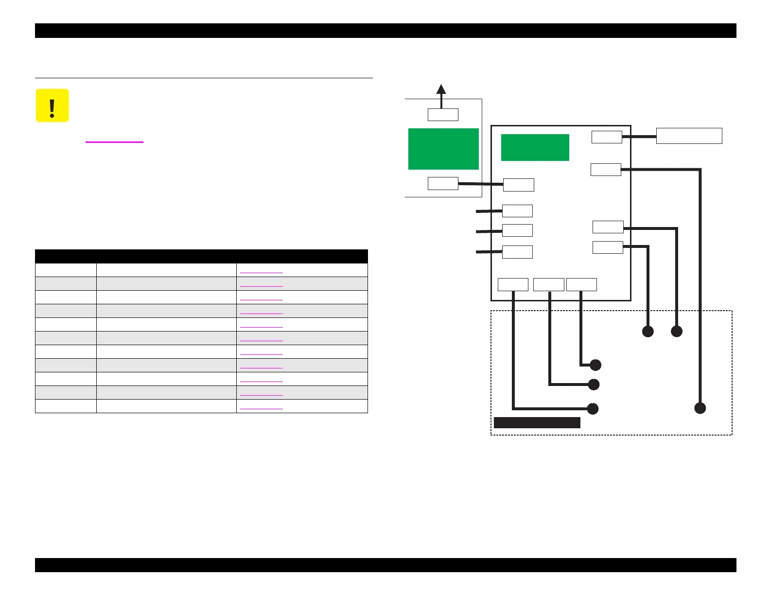
A.2 Connector Summary (Stylus COLOR 740)
The followin
table lists the connectors used on the C257MAIN board of
the St
lus COLOR 740. The fi
ure at ri
ht shows how the components
are connected. Each connector’s pin assi
nments are detailed in the
tables on the followin
pa
es.
Figure A-2. Cable Connections in the Stylus COLOR 740
CAUTION
The connector information contained in this section
applies only to the Stylus COLOR 740. If you need
information on the Stylus COLOR 440 or 640, refer to
Section A.1
.
Table A-13. Main Board Connector Summary
Connector Function Pin Assignments
CN1 To parallel I/F Table A-14
CN2 To serial I/F Table A-15
CN3 To USB I/F Table A-16
CN4 To HP sensor Table A-17
CN5 To PE sensor Table A-18
CN6 To ASF sensor Table A-19
CN7 To CR motor Table A-20
CN8 To PF motor Table A-21
CN9 To printhead Table A-24
CN10 To power supply board Table A-22
CN11 To control panel Table A-23
CN1
CN2
AC
CN10
CN11
CN9
C257MAIN
(M ain B oard)
CN1
CN2
CN7
CN8
CN6
CN4
CN5
C ontrol P anel
Printhead
CR
Motor
PF
Motor
ASF Sensor
HP Sensor
PE Sensor
P a ra lle l I/F
S e ria l I/F
Printer M echanism
C257PSB/PSE
C257PSK
(Pow er Supply
Board)
CN3
USB I/F
 Loading...


