EPSON Stylus COLOR 440, 640, and 740 Appendix
150
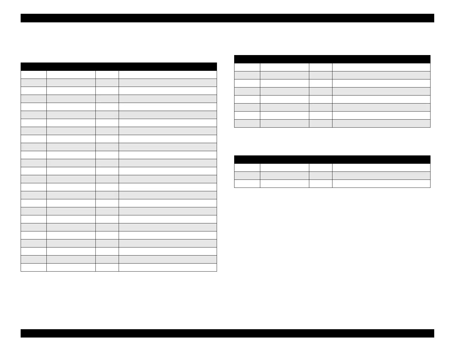
Table A-10. Printhead Connector (CN8)
(Stylus COLOR 640: C256MAIN only)
Pin Signal Name I/O Function
1 BCO In Black ink cartridge detect signal
2 CCO In Color ink cartridge detect signal
3 THM In Thermistor sensor output
4 GND — Ground
5 LAT Out Head data latch pulse output
6 GND — Ground
7 SI3 Out Head data output (3)
8 GND — Ground
9 SI2 Out Head data output (2)
10 GND — Ground
11 SI1 Out Head data output (1)
12 GND — Ground
13 CLK Out Clock pulse for head data transfer
14 GND — Ground
15 NCHG Out Head all on pulse output
16 GND — Ground
17 VDD — Logic power supply (+5V)
18 GND2 — Ground
19 GND2 — Ground
20 GND2 — Ground
21 COM — Head drive power supply
22 COM — Head drive power supply
23 COM — Head drive power supply
24 VHV — Head drive voltage control signal
25 VHV — Head drive voltage control signal
Table A-11. Power Supply Connector (CN10)
Pin Signal Name I/O Function
1 +42 V — Mechanism drive power supply
2 +42 V — Mechanism drive power supply
3 GND — Ground
4 GND — Ground
5 PSC Out Power supply switch output signal
6 GND — Ground
7 GND — Ground
8 +5 V — Logic power supply
Table A-12. ASF Sensor Connector (CN11)
Pin Signal Name I/O Function
1 ASF In Sensor detect signal
2 GND — Ground
3 ASFV — Sensor power supply (+5 V)
 Loading...


