EPSON Stylus COLOR 440, 640, and 740 Chapter 2 Operating Principles
59
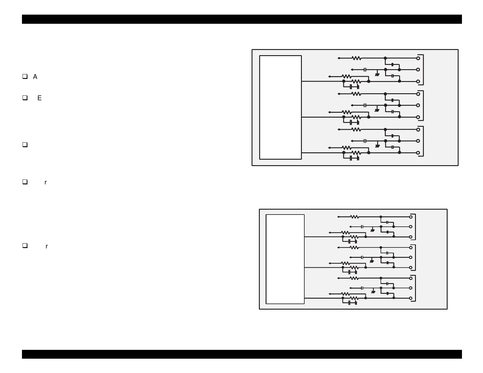
Sensor Circuits
The printer mechanism includes 3 sensors. As shown in the followin
fi
ures, the
connect directl
to the
ate arra
IC2
.
ASF Sensor
The ASF sensor detects the home position of the auto sheet feeder.
PE Sensor
The PE sensor determines if there is paper in the printer. In
addition, if paper of non-standard len
th is inserted into the printer,
the PE sensor detects its ed
e and prevents printin
from takin
place on the bare platen.
HP Sensor
The HP sensor detects the home position of the carria
e.
The followin
sensors are part of the printhead and carria
e unit.
Thermistor
The thermistor detects printhead temperature and maintains print
ualit
despite chan
es in environmental conditions. When the
thermistor heats up, its resistance chan
es and a correspondin
volta
e rela
s this information to the CPU. The
ate arra
makes
sli
ht ad
ustments to the PZT drive volta
e based on this
information, and print
ualit
is maintained.
Cartrid
e Sensors
Black, Color
Sensors built into the carria
e unit detect the presence of the ink
cartrid
es durin
cartrid
e replacement and when the power is
turned on. This information is received b
the
ate arra
. In the
St
lus COLOR 440, 640, and 740 printers, ever
time the black or
color ink cartrid
e is removed, its respective ink consumption
counter
ets reset.
NOTE: Ink consumption is not detected by a sensor. Rather, it is
calculated from the same EPW data that the printer sends to the host.
Figure 2-29. Figure 5-23. Sensor Circuit for Stylus COLOR 440
Figure 2-30. Figure 5-24. Sensor Circuit for Stylus COLOR 640
IC 2
E05B44
+5V
+5V
CN11
CN5
CN4
ASF
HP
PE
PE
GND
PEV
HP
GND
HPV
ASF
GND
ASFV
+5V
+5V
+5V
+5V
+5V
+5V
+5V
206
SW4
204
SW5
202
SW6
IC 2
E05B 43
+5V
+5V
CN11
CN5
CN4
ASF
HP
PE
PE
GND
PEV
HP
GND
HPV
ASF
GND
ASFV
+5V
+5V
+5V
+5V
+5V
+5V
+5V
206
SW 4
204
SW 5
202
SW 6
 Loading...


