EPSON Stylus COLOR 440, 640, and 740 Chapter 2 Operating Principles
37
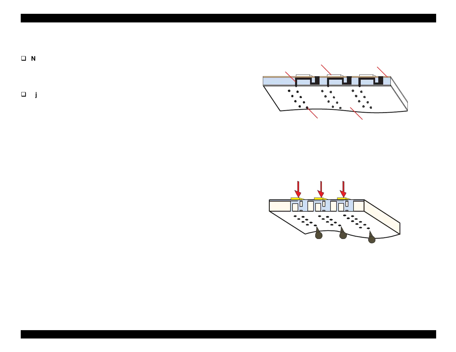
The followin
fi
ures show sectional drawin
s of the printhead while
waitin
to print and durin
printin
normal state and e
ectin
state
.
Normal State:
Durin
the normal state, the PZT elements do not move and ink fills
the ducts between the ink cavit
and the nozzles.
Refer to Fi
ure
2-3.
Ejecting State:
The printhead is desi
ned to operate at a hi
h fre
uenc
, and
oes
throu
h thousands of print c
cles each second. Durin
each print
c
cle, the main board transmits data to the nozzle selector IC
IR2C72C
, which is located on the printhead. This data determines
which PZTs are to be actuated in the current c
cle. At the same
time, the main board
enerates a hi
h-fre
uenc
drive volta
e.
Durin
each print c
cle, the nozzle selector applies this drive
volta
e to specific PZTs, as determined b
the print data. This
causes ink to e
ect from the nozzles in a specific pattern.
See
Fi
ure 2-4.
Figure 2-3. Printhead - Normal State
Figure 2-4. Printhead - Ejecting State
Nozzle
Nozzle Plate
Cavity
PZT
Ink Course
 Loading...


