EPSON Stylus COLOR 440, 640, and 740 Chapter 2 Operating Principles
61
Common Voltage Drive Circuit
The common volta
e drive circuit
enerates the volta
e waveform for
drivin
the PZTs
piezo-electric elements
in the printhead. The
ate
arra
outputs si
nals to the common drive IC
H8D2813, H8D2889, or
CXA20995 in the St
lus COLOR 440, 640, or 740
. The common drive
IC then drives 2 power transistors arran
ed in a push-pull confi
uration
see Fi
ures 2-32 throu
h 2-34 below
. The waveform produced b
these transistors is called the “trapezoidal” waveform, because it looks
like an irre
ularl
shaped trapezoid with a small step in the middle. The
trapezoidal waveform can be observed an
time the printer is on,
whether somethin
is bein
printed or not.
Table 2-9. Common Voltage Driver Characteristics
Nozzle Selector Drive Circuit
The nozzle selector IC is located in the printhead itself. Data from the
ate arra
is sent seriall
to the IC and latched in one-b
te units. After
the IC interprets the data, it sends print si
nals in parallel to the
appropriate PZTs. These si
nals are s
nchronized with the trapezoidal
waveform produced b
the common volta
e driver, and determine
which PZTs
et actuated b
the common volta
e in each c
cle.
Fi
ure 2-32, Fi
ure 2-33, and Fi
ure 2-34 show printhead driver
dia
rams for each printer.
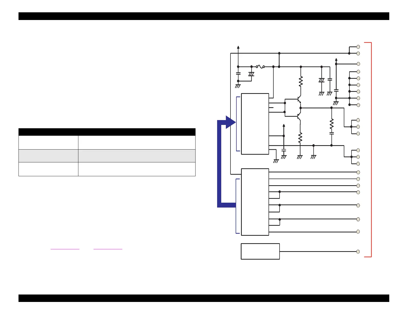
Figure 2-32. Head Drive Circuit for Stylus COLOR 440
Items Characteristics
Drive voltage 42 volts
±
5%
Waveform appears after voltage rises above 5 volts.
Final drive element
(power transistors)
2S
C3746
(PNP)
2S
A1469
(NPN)
Operation during reset Both transistors are off.
H8D2813(IC6)
XOVM
CTB
COM
DTB
GND
GND
25
1
20
+5
F1
+42
22
23
VHV
VHV
+5
GND
GND
GND
GND
GND
GND
VDD
15
14
12
10
8
6
4
COM
COM
COM
19
21
20
GND2
GND2
GND2
16
18
17
E05B44(IC2)
VHCTL
2
4
6
199
CCO
LAT
SI1
SI2
CLK
NCHG
BCO
THM
1
2
5
9
7
11
3
13
200
198
SW7
SW8
90
LP
99
100
BIEN
BHSO
YCMHSO
97
96
YCMIEN
ICLK
BCHCLK
/NCHG
93
92
89
TMP95C061(IC1)
AN0
20
CN8
CHG
KC1
ND1
ND2
MD1
MD2
Data
CLK
/STB
/CLR
VRF
VK
CHG
KC1
ND1
ND2
MD1
MD2
Data
CLK
/STB
/CLR
VRF
VK
VHCTL
Vcc
 Loading...


