EPSON Stylus CX4900/CX4905/CX5000/DX5000/DX5050/CX5900/CX6000/DX6000/DX6050 Revision A
DISASSEMBLY/ASSEMBLY Printer Section 134
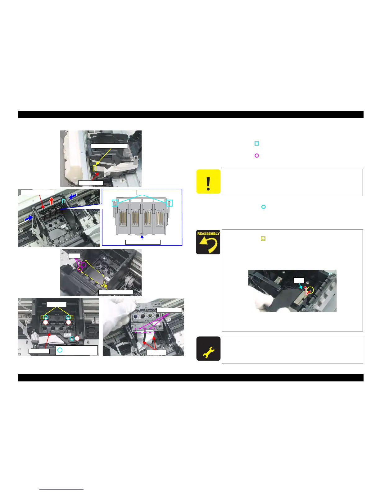
Figure 4-11. Removing Printhead (2)
8. Disconnect the Head FFCs (x2) that are connected to the CSIC Board and the
CR Encoder Board.
9. Release the tabs (x2, ) that secure the Holder Board Assy, and remove the
Holder Board Assy upward.
10. Release the tabs (x2, ) that secures the Sub FFC Guide with a precision
screwdriver (-), and remove the Sub FFC Guide.
11. Rem
ove the screws (x3, ) that secure the Print Head, and lift up to remove
Printhead with a longnose pliers.
12. Disconnect the Head FFCs (x2) from the connectors (x2) of the Print Head,
and remove the Printhead.
Tabs
Sub FFC Guide
C.B.P. 2.5x8 F/Zn
(3±1kgfcm)
1
2
3
Guide Pins
Printhead
Head FFC
Connectors
CSIC Connector
Head FFC
Holder Board Assy Tabs
Holder Board Assy
C A U T I O N
Do not touch or damage the nozzles or the ink supply needles of the
Printhead.
When installing the Printhead to the Carriage Unit, match the
guide pins (x2,
) of the Carriage Unit with the positioning holes
(x2) of the Printhead.
Tighten the scre
ws in the order as shown in the figure.
Wh
en installing the Sub FFC Guide, insert the rib of the Sub
FFC Guide to the notch of the Carriage Unit as shown below.
Figure 4-12. Installing Sub FFC Guide
When installing the Holder Board Assy, insert it vertically,
making sure that it does not strand onto the rib of the Printhead.
A D J U S T M E N T
R E Q U I R E D
After removing/replacing the Printhead, perform the adjustment
referring to Table 5-1."Required Adjustments" (p172)
Rib

 Loading...


