EPSON Stylus CX4900/CX4905/CX5000/DX5000/DX5050/CX5900/CX6000/DX6000/DX6050 Revision A
DISASSEMBLY/ASSEMBLY Printer Section 150
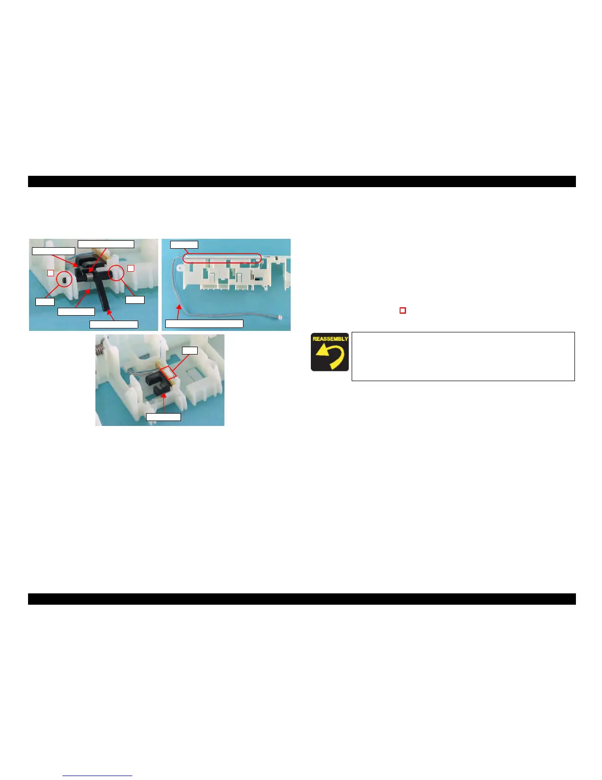
4.4.16 PE Sensor Board/PE Sensor Lever
External view
Figure 4-33. Removing PE Sensor Board/PE Sensor Lever
Part/Unit
that should be removed before removing PE Sensor Board/
PE Sensor Lever
Document Cover / Panel Unit / Scanner Unit / Housing, Upper / Housing, Lower /
ASF Unit / Holder Shaft Unit / Spur Gear 36.8 / Extension Spring 0.143 / Clutch
Removal procedure
1. Remove the shaft of the PE Sensor Lever from the Holder Shaft, and remove
the PE Sensor Lever and Torsion Spring 0.22 in the order as shown in the
figure.
2. Remove Torsion Spring 0.22 from the PE Sensor Lever.
3. Release the PE Sensor Connector Cable from the groove of the Holder Shaft.
4. Release the tab (x1, ) that secures the PE Sensor, and remove the PE Sensor
from the Holder Shaft.
PE Sensor Lever
Straight Tip
L-shaped Tip
Torsion Spring 0.22
Shaft
1
2
Shaft
PE Sensor Connector Cable
Groove
PE Sensor
Tab
Fasten the L-shaped tip of Torsion Spring 0.22 to the concave
portion of the PE Sensor Lever, and fasten the straight tip to the
Holder Shaft.
Route the PE Sensor Connector Cable to the groove of the
Holder Shaft so that the Cable does not run off.

 Loading...


