EPSON Stylus CX4900/CX4905/CX5000/DX5000/DX5050/CX5900/CX6000/DX6000/DX6050 Revision A
DISASSEMBLY/ASSEMBLY Scanner Section 168
4.5.3 Scanner Motor Unit/Scanner HP Sensor/
Driven Pulley
External view
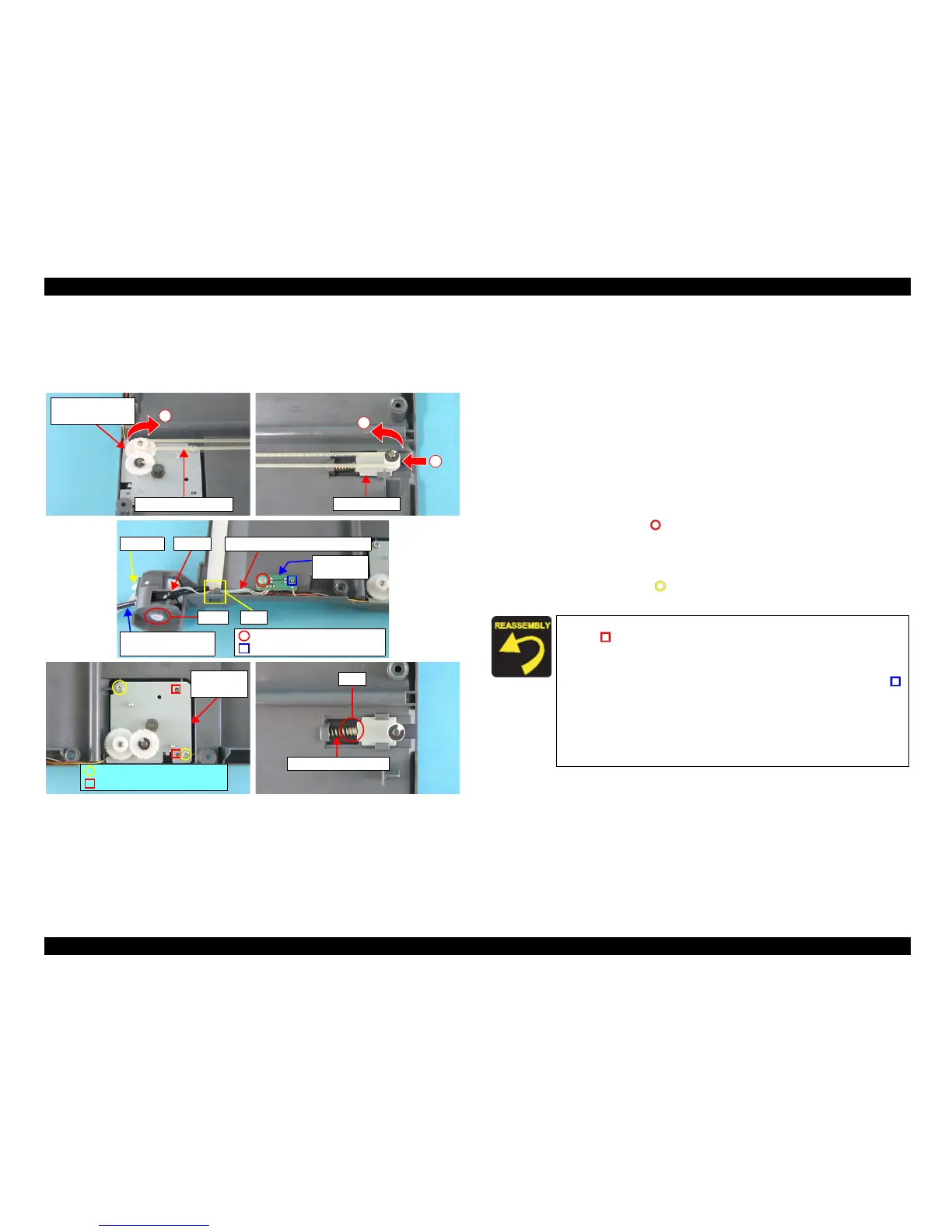
Figure 4-58. Removing Scanner Motor Unit/Scanner HP Sensor/
Driven Holder
Part/Unit
that should be removed before removing Scanner Motor Unit/
Scanner HP Sensor/Driven Holder
Document Cover / Panel Unit / Scanner Unit / Scanner Housing, Upper
Removal procedure
1. Move the Scanner Carriage Unit to the center of the Scanner Unit.
2. Push the Driven Holder to the direction of the arrow, and remove Compound
Gears 22.8, 7.762, Driven Holder, and Scanner Timing Belt.
3. Release the shaft of the hinge L from the bearing of the Scanner Housing,
Lower.
4. Disconnect the Scanner Connector Cable and the Scanner HP Sensor
Connector Cable from the tab of the hinge L, and pull them out from the notch
of the Scanner Housing, Lower.
5. Remove the screw (x1, ) that secures the Scanner HP Sensor, and remove
the Scanner HP Sensor.
6. Release the Scanner Motor Connector Cable and the Scanner HP Sensor
Connector Cable from the tab of the Scanner Housing, Lower.
7. Remove the screws (x2, ) that secure the Scanner Motor Unit, and remove
the Scanner Motor Unit.
1
3
Driven Holder
Compound Gears
22.8, 7.762
2
Scanner Timing Belt
Hinge L
Scanner Motor Connector Cable
Notch
Scanner HP Sensor
Connector Cable
C.B.P 3x8 F/Zn (5±1kgfcm)
É_É{
Scanner HP
Sensor
C.B.P. 3x8 F/Zn (5±1kgfcm)
Guide Pin
Tab
Shaft
Scanner
Motor Unit
C.B.P. 3x8 F/Zn (5±1kgfcm)
Guide Pins
Rib
Driven Holder Spring
When installing the Scanner Motor Unit, match the guide pins
(x2,
) of the Scanner Housing, Lower with the positioning holes
(x2) of the Scanner Motor Unit.
When installing the Scanner HP Sensor, match the guide pi
n (x1)
of the Scanner Housing, Lower with the positioning hole (x1, )
of the Scanner
HP Sensor.
Route
the Scanner Motor Connector Cable and the Scanner HP
Sensor Connector Cable as shown in the figure.
Insert the Driven Holder Spring into the rib of the Driven
Holder.

 Loading...


