EPSON Stylus CX4900/CX4905/CX5000/DX5000/DX5050/CX5900/CX6000/DX6000/DX6050 Revision A
DISASSEMBLY/ASSEMBLY Printer Section 152
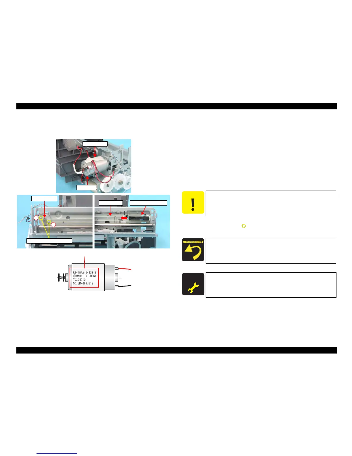
4.4.18 CR Motor
External view
Figure 4-36. Removing CR Motor
Part/Unit
that should be removed before removing CR Motor
Document Cover / Panel Unit / Scanner Unit / Housing, Upper / Housing, Lower /
Main Board Unit / CR Guide Frame
Removal procedure
1. Slide the Carriage Unit to the center of the printer.
2. Peel off the acetate tape (x1) from the CR Motor, and release the CR Motor
Connector Cable and the PF Motor Connector Cable.
3. Release the CR Motor Connector Cable from the tab of the ASF Unit.
4. Loosen the tension of the Timing Belt by pressing the Driven Pulley Holder in
the direction of the arrow as shown in the figure, and remove the Timing Belt
from the pinion gear of the CR Motor.
5. Remove the s
crews (x2, ) that secure the CR Motor, and remove CR Motor
from the Printer Mechanism.
Acetate Tape
CR Motor
Driven Pulley Holder
Timing Belt
Pinion Gear
C.P. 3x4 F/Zn (4±0.5kgfcm)
1
2
Lot No.
C A U T I O N
Do not damage the pinion gear of the CR Motor.
Install the CR Motor so that the Lot Number faces upward.
Tighten the screws in the order as shown in the figure.
Make sure that there is no gap between the CR Motor and the
Main Frame.
A D J U S T M E N T
R E Q U I R E D
After removing/replacing the CR Motor, perform the adjustment
referring to Table 5-1."Required Adjustments" (p172)

 Loading...


