EPSON Stylus CX4900/CX4905/CX5000/DX5000/DX5050/CX5900/CX6000/DX6000/DX6050 Revision A
OPERATING PRINCIPLES Electrical Circuit Operating Principles 83
2.4.2 C657 Main Board
The logic circuit of the C657 Main Board is composed of the follows;
Logic line (CPU-ASIC 2 in 1, SDRAM, P-ROM and so on)
Motor control/drive circuit (CR Motor, PF Motor, Scanner Motor)
Head control/drive circuit
USB Interface control circuit
Sensor circuit
Combination circuit (RTC circuit, Reset circuit, EEPROM circuit)
The printer mechanism is controlled by the above circuits. Following explains the
major characteristics of this Main Board.
Lithi
um battery is not mounted
Ado
ption of 3.3V/1.5V drive logic circuit components
The 5V formed by the Combination Motor Driver (IC5) of C657 Main Board is
stepped down to 3.3V by the Regulator (IC6), and it is then used as drive voltage
for many elements. In addition, when SPC shifts to low power mode, the 3.3V that
was stepped down by the Regulator (IC6) is stepped down to 1.5V by the
Combination Motor Driver (IC5) and elements that had been driven by 3.3V are
driven by 1.5V for suppression of power consumption.
2.4.2.1 Main Elements
Table 2-9 (p.83) shows the function of the each main elements on C657 Main Board.
Note "*": Only for Stylus CX4700/CX4800/DX4800/DX4850.
Table 2-8. 3.3V/1.5V & 5V Drive Components
5VDC 3.3 VDC 3.3/1.5VDC
• RTC (IC4) • Flash ROM (IC1)
• Card ASIC(IC9)
• SDRAM (IC2)
• CPU-ASIC (IC8)
• Motor driver (IC5)
• Common driver (IC7)
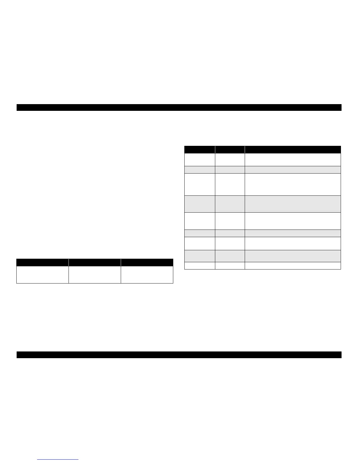
Table 2-9. Main Elements
IC Location Function
Flash ROM IC1
16Mbit
• Firmware storage
SDRAM IC2 Bus= 16 bit, 128Mbit DRAM
RTC IC4
•EEPROM
Default setting
s, backup for all parameters
• Reset function
•Timer function
CPU-ASIC IC8
CPU mounted on the MAIN board is driven by clock
frequency 48 MHz, 96MHz and controls the printer and
scanner, SDRAM.
Motor Driver IC5
• CR/PF/Scanner motor drive IC
• Dropping 42V line to 5V
• Dropping 3.3V line to 1.5V
Regulator IC6 Dropping 5V line to 3.3V
Common Driver IC7
Head drive control HIC
• Generates head common voltage.
AD converter IC11
Analog data from the scanner unit is converted into
digital data.
Card ASIC
*
IC9 Control the Memory Card slot.

 Loading...


