EPSON Stylus CX4900/CX4905/CX5000/DX5000/DX5050/CX5900/CX6000/DX6000/DX6050 Revision A
DISASSEMBLY/ASSEMBLY Printer Section 139
4.4.10 PS Board Unit
External view
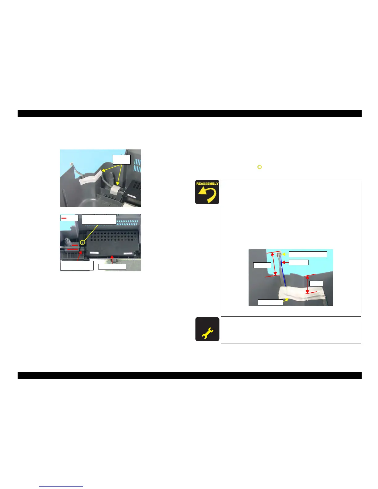
Figure 4-18. Removing PS Board Unit
Part/Unit
that should be removed before removing PS Board Unit
Document Cover / Panel Unit / Scanner Unit / Housing, Upper /
Printer Mechanism
Removal procedure
1. Peel off the acetate tapes (x2) that secure the PS Connector Cable.
2. Remove the screw (x1, ) that secures the PS Board Unit, and remove the PS
Board Unit.
Acetate
Tapes
C.B.P. 3x10 F/Zn
(4±1kgfcm)
Ferrite Core and
Dent
Rib
PS Board Unit
Place the Ferrite Core to the dent of the Housing, Lower.
Route the PS Connector Cable between the ribs of the Housing,
Lower, and secure them with acetate tape.
When r
outing the PS Connector Cable between the ribs of the
Housing, Lower, pay attention to the following instructions.
• The gap between the PS Connector Cable and the Edge of the
Housing. Lower should be 15 mm.
• The PS Connector Cable should be run off the edge of the
Housing, Lower for 40 ± 2 mm.
• The blue line of the PS Connector Cable should be facing rear
of the Housing, Lower.
Figure 4-19. Routing PS Connector Cable
A D J U S T M E N T
R E Q U I R E D
After replacing the PS Board Unit, perform the adjustment
referring to Table 5-1."Required Adjustments" (p172)
40±2mm
Red Line
15mm
PS Connector Cable
Acetate Tape

 Loading...


