EPSON Stylus CX4900/CX4905/CX5000/DX5000/DX5050/CX5900/CX6000/DX6000/DX6050 Revision A
DISASSEMBLY/ASSEMBLY Removal procedure Specific to Stylus CX4900/CX4905/CX5000/DX5000/DX5050 169
4.6 Removal procedure Specific to Stylus CX4900/
CX4905/CX5000/DX5000/DX5050
4.6.1
Panel Unit
External view
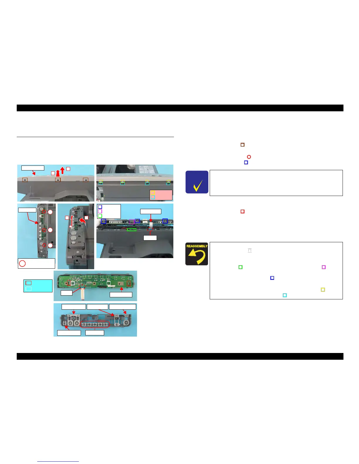
Figure 4-59. Removing Panel Unit
Part/Unit
that should be removed before removing Panel Unit
None
Removal procedure
1. Release the tabs (x3, ) that secure the Panel Cover with a precision
screwdriver (-), and remove the Panel Cover in the order shown in the figure.
2. Remove the screws (x3, ) that secure the Panel Unit.
3. Release the hooks (x3, ) of the Panel Unit in the order shown in the figure.
4. Di
sconnect the Panel FFC from the Main Board Connector (CN12), and
remove the Panel Unit.
5. Release the tabs (x2, ) that secure the Panel Board, and remove the Panel
Board.
6. Disconnect the Panel FFC from the connector (CN1) of the Panel Board.
7. Remove S-Buttons (x5), Copy-Button, Stop-Button, Ink-Button, and Power-
Button from the Panel Housing.
Panel FFC
CN12
Tabs
Rib
Notch
Panel Cover
1
2
C.B.S. 3x8 F/Zn
(7±1kgfcm)
Panel Unit
1
2
3
Panel Board
CN1
Tab
Guide Pin
Tabs
Notches
S-Button
Power-ButtonCopy-Button
Stop-Button
Ink-Button
12
C H E C K
P O I N T
When removing the Panel Unit, disconnect the Panel FFC from the
Main Board side (CN12).
When installing the Panel Board to the Panel Housing, match the
guide pins (x2,
) of the Panel Housing with the positioning
holes (x2) of the Panel Board.
W
hen installing the Panel Unit to the Housing, Upper, match the
notch (x1, ) of the Housing, Upper with
the rib (x1, ) of the
Panel Unit. The notches of the Housing, Upper should also be
matched with the tabs (x3, ) of the Panel Unit.
Tighten the scre
ws in the order as shown in the figure.
When
installing the Panel Cover, match the tabs (x4, ) of the
Panel Cover and the notches (x4,
) of the Panel Unit.

 Loading...


