EPSON Stylus CX4900/CX4905/CX5000/DX5000/DX5050/CX5900/CX6000/DX6000/DX6050 Revision A
DISASSEMBLY/ASSEMBLY Printer Section 146
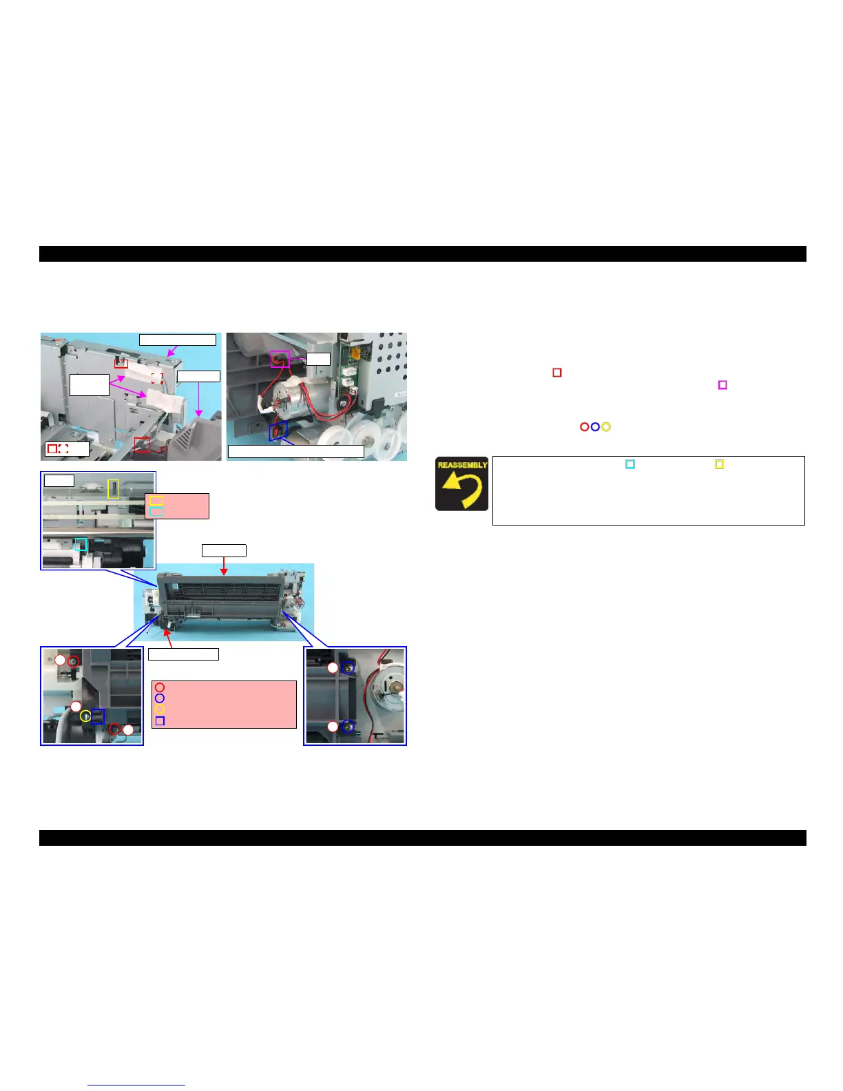
4.4.13 ASF Unit
External view (1)
Figure 4-27. Removing ASF Unit (1)
Part/Unit
that should be removed before removing ASF Unit
Document Cover / Panel Unit / Scanner Unit / Housing, Upper / Housing, Lower
Removal procedure
1. Peel off the acetate tape (x1) that secures the PE Sensor Connector Cable to
the shield plate of the Main Board, and release PE Sensor Connector Cable
from the tabs (x3, ) of the ASF Unit and the Main Board Unit.
2. Release the CR Motor Connector Cable from the tab (x1, ) of the ASF Unit.
3. Remove the Ferrite Core of the PF Motor Connector Cable from the slot of the
ASF Unit.
4. Remove the screws (x5, ) that secure the ASF Unit, and remove the
ASF Unit from the Printer Mechanism.
Ferrite Core (PF Motor) and Slot
Tab
1
3
5
2
4
ASF Unit
C.B.S. 3x6 F/Zn (8±1kgfcm)
C.B.S.(P2) 3x6 F/Zn (8±1kgfcm)
C.B.P. 3x8 F/Zn (4±1kgfcm)
Shaft and Slot
Ink System Unit
Front
Rib
ASF Unit
Acetate
Tapes
Tabs
Main Board Unit
Guide Pin
Match the guide pin (x1, ) and the rib (x1, ) of the ASF Unit
with the positioning holes (x2) of the Main Frame.
Insert the
shaft of the ASF Unit into the slot of the Ink System
Unit.
Tighten the screws in the order as shown in the figure.

 Loading...


