EPSON Stylus CX4900/CX4905/CX5000/DX5000/DX5050/CX5900/CX6000/DX6000/DX6050 Revision A
ADJUSTMENT Adjustment Except Adjustment Program 186
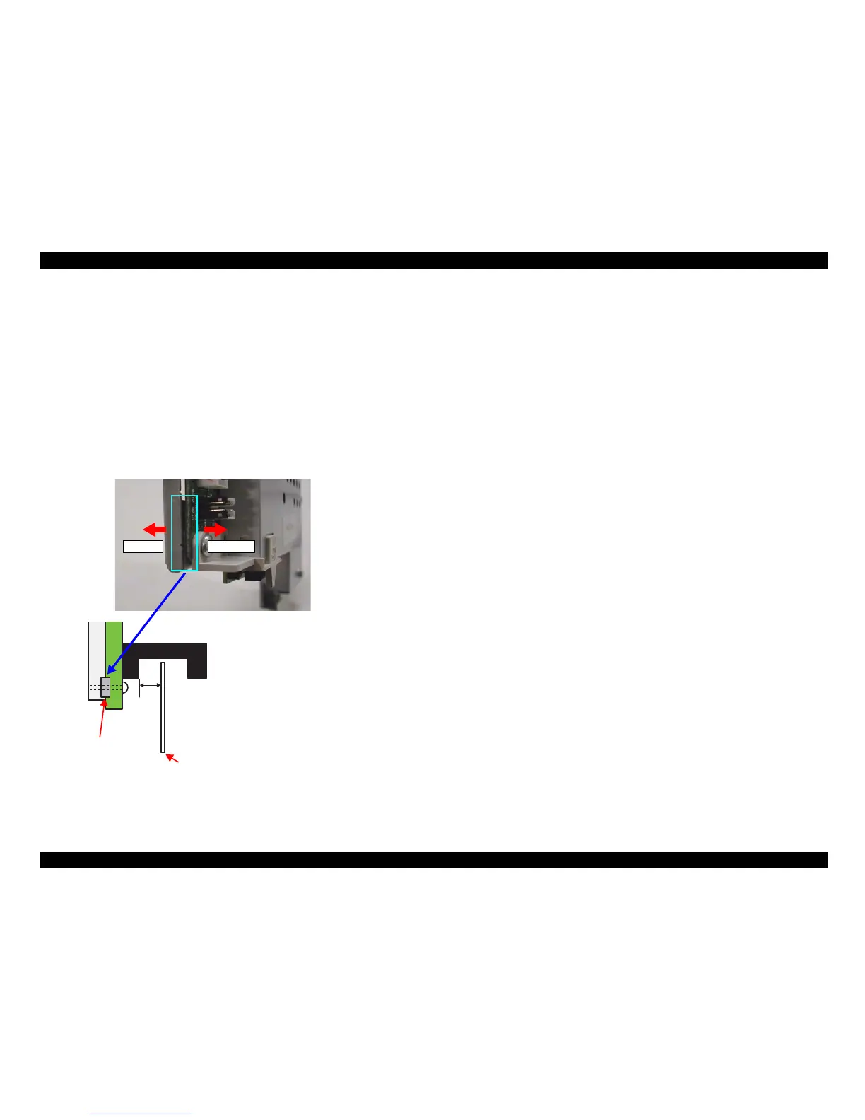
5.3.2 PF Scale Sensor Positioning Adjustment
Parts to be Removed and Replaced
Replacement of Main Board Unit
Replacement of PF Roller Unit
Adjustment procedure
1. Test fit Main Board Unit, and confirm whether or not PF Scale is positioned
in the center of PF Sensor.
2. If PF Scale is positioned in the center of PF Sensor, adjustment is complete. If
scale is not positioned in center of sensor, adjust position of PF Scale using
spacer (0.5mm thickness) as shown in diagram below.
Figure 5-23. PF Scale Sensor positioning adjustment
Left side Right side
0.1 to
1.0mm
Spacer
PF Scale
Spacer is not applied to Main
Board Unit for service part.
Place spacer between Shield
Board and Main Board.
If PF Scale is off to the left,
remove the spacer.
If PF Scale is off to the right,
add an additional spacer.
(Total of 2 spacers)

 Loading...


