EPSON Stylus CX4900/CX4905/CX5000/DX5000/DX5050/CX5900/CX6000/DX6000/DX6050 Revision A
DISASSEMBLY/ASSEMBLY Printer Section 158
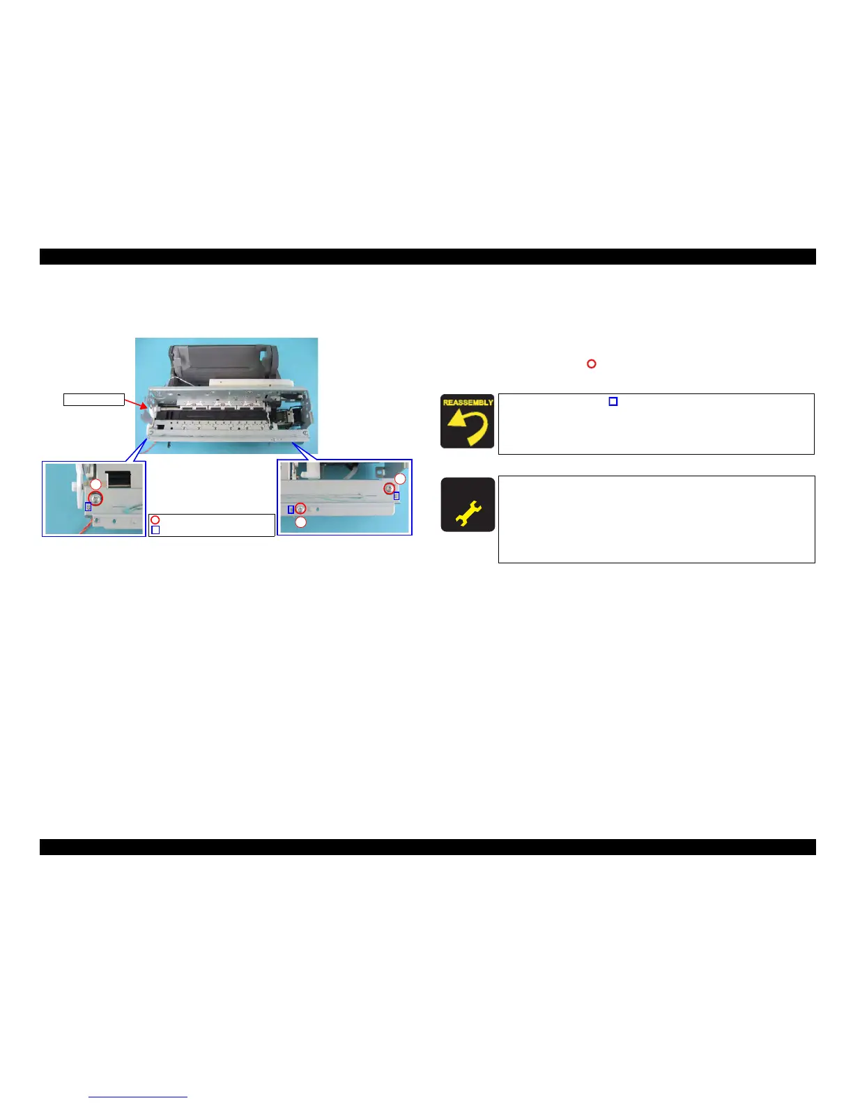
4.4.22 Front Frame
External view
Figure 4-43. Removing Front Frame
Part/Unit
that should be removed before removing Front Frame
Document Cover / Panel Unit / Scanner Unit / Housing, Upper / Housing, Lower /
Main Board Unit / CR Guide Frame / CR Motor / CR Scale / Carriage Unit
Removal procedure
1. Remove the screws (x3, ) that secure the Front Frame, and remove the
Front Frame from the Printer Mechanism.
2
1
3
Front Frame
C.B.S. 3x6 F/Zn (7±1kgfcm)
Ribs
Match the ribs (x3, ) of the Main Frame with the positioning
holes of the Front Frame.
Tighten the screws in the order as shown in the figure.
A D J U S T M E N T
R E Q U I R E D
After replacing the Front Frame with a new one, always apply
grease KEN to the specified parts.
• Refer to Figure 6-9 (p194) for details.
After removing/replacing the Front Frame, perform the
adjustment referring to Table 5-1."Required Adjustments"
(p172)

 Loading...


