EPSON Stylus CX4900/CX4905/CX5000/DX5000/DX5050/CX5900/CX6000/DX6000/DX6050 Revision A
OPERATING PRINCIPLES Electrical Circuit Operating Principles 86
2.4.2.3 Motor Driver Circuit
CR/PF Motor drive circuit
The motor driver IC (IC5) on the Main board drives CR/PF Motor. This product uses
DC motor and performs constant current PWM drive.
Based on the output pulse (signal) from CR Encoder or PF Encoder, the CPU (IC8) sets
the appropriate drive current value for each operational action and outputs the value as
a special control signal to the Motor Driver (IC5). Then, based on the signal output
from the CPU, the Motor Driver outputs the motor drive current to the CR/PF Motor.
When no data has been received for 5 minutes, the CPU sets the Motor Driver current
value to 0, turning off the Motor Driver, in order to conserve electricity.
Scanner Motor Driver Circuit
The motor driver IC (IC5) on the Main board drives Scanner Motor. This product uses
PM type stepping motor and performs constant current bi-polar drive.
The Motor Driver IC (IC9) forms the motor drive waveform based on the signal output
from the CPU (IC8), controlling the Scanner Motor.
When no data has been received for 5 minutes, the CPU sets the Motor Driver current
value to 0, turning off the Motor Driver, in order to conserve electricity.
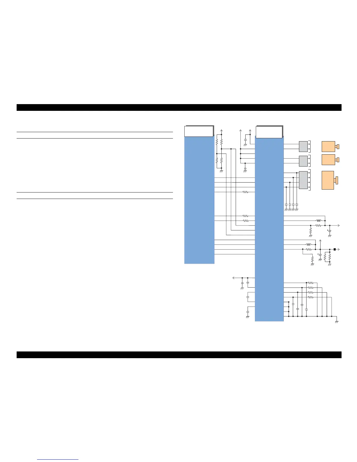
Figure 2-19. Motor Driver Circuit Block Diagram
CPU
(IC8)
Motor Driver
(IC5)
SCLK1_DCMCU

 Loading...


