EPSON Stylus CX4900/CX4905/CX5000/DX5000/DX5050/CX5900/CX6000/DX6000/DX6050 Revision A
DISASSEMBLY/ASSEMBLY Printer Section 153
4.4.19 PF Motor
External view
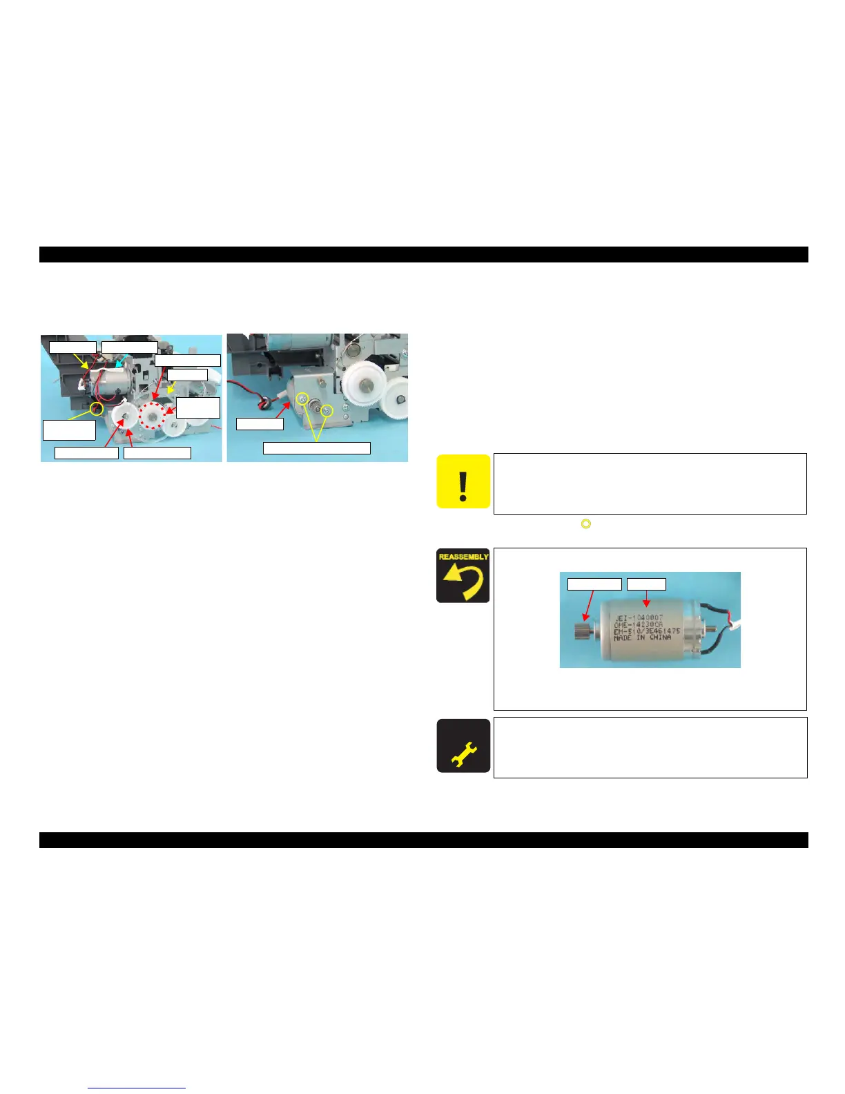
Figure 4-37. Removing PF Motor
Part/Unit
that should be removed before removing PF Motor
Document Cover / Panel Unit / Scanner Unit / Housing, Upper / Housing, Lower /
Main Board Unit
Removal procedure
1. Peel off the acetate tape (x1) from the CR Motor, and release the CR Motor
Connector Cable and the PF Motor Connector Cable.
2. Remove the Ferrite Core (x1) of the PF Motor Connector Cable from the slot
(x1) of ASF Unit.
3.
Remove the PF Scale that is secured with double-sided tape to the Spur Gear 32.4.
4. Remove the Spacer (4.1 x 0.5) that secures Spur Gear 30.8, and remove Spur
Gear 30.8 from the Main Frame.
5. Rem
ove the screws (x2, ) that secure the PF Motor, and remove the PF
Motor from the Printer Mechanism.
PF Motor
C.P. 3x4 F/Zn (4±0.5kgfcm)
Ferrite Core
and Slot
Acetate TapeCR Motor
PF Scale
Double-
sided Tape
Spur Gear 32.4
Spur Gear 30.8
Spacer (4.1x0.5)
C A U T I O N
Do not damage the following parts.
Pinion gear of
the PF Motor
PF Scale
Spur Gear 30.8
Install the PF Motor so that the Lot Number faces upward.
Figure 4-38. Installing PF Motor
Make sure that there is no gap between the PF Motor and the
Main Frame.
A D J U S T M E N T
R E Q U I R E D
After removing/replacing the PF Motor, perform the adjustment
referring to Table 5-1."Required Adjustments" (p172)
Pinion Gear
Lot No.

 Loading...


