EPSON Stylus CX4900/CX4905/CX5000/DX5000/DX5050/CX5900/CX6000/DX6000/DX6050 Revision A
APPENDIX Connector Summary 198
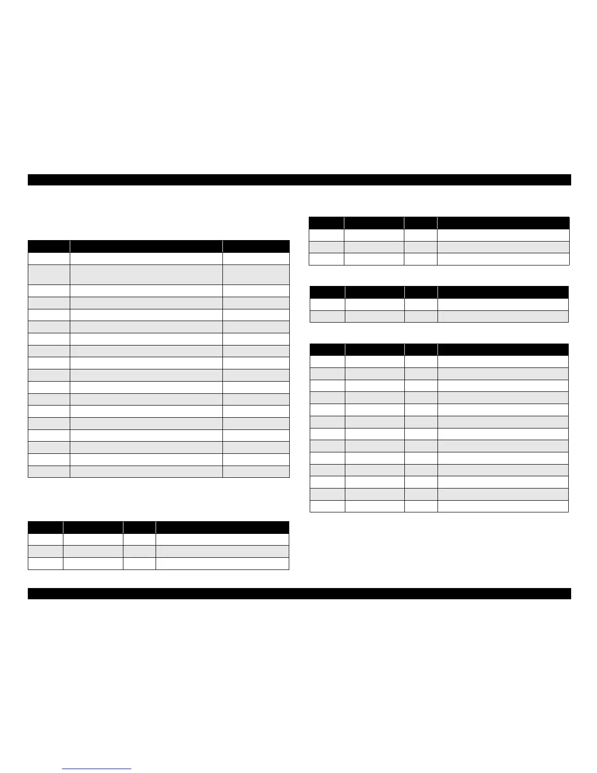
See the following tables for the connector summary for the C657 Main board and each
connectors pin alignment.
Note *1: Stylus CX4900/CX4905/CX5000/DX5000/DX5050 only
*2: Stylus CX5900/CX6000/DX6000/DX6050 only
Table 7-1. Connector Summary for C657 Main Board
Connector Function Table to refer to
CN1 For connection with the Power Supply Board
Table 7-2 (p.198)
CN2 For connection with the USB2.0 interface
“1.3.1 USB
Interface” (p.20)
CN3 For connection with the PE Sensor Table 7-3 (p.198)
CN4 For connection with the PG Sensor Table 7-4 (p.198)
CN5 For connection with the Print Head
Table 7-5 (p.198)
CN6 For connection with the Print Head Table 7-6 (p.199)
CN7 For connection with the C654 HEAD Board Table 7-17 (p.202)
CN8 For connection with the CR Motor Table 7-8 (p.199)
CN9 For connection with the PF Motor Table 7-9 (p.199)
CN10 For connection with the Scanner Motor Table 7-10 (p.199)
CN11 For connection with the Scanner Carriage FFC
Table 7-11 (p.199)
CN12*
1
For connection with the Panel Board (C571 PNL) Table 7-12 (p.200)
CN13 For connection with the Scanner HP Sensor Table 7-13 (p.200)
CN14 For connection with the Memory Card Table 7-14 (p.200)
CN15 For connection with the Memory Card
Table 7-15 (p.201)
CN16 For connection with the USB Host I/F Board Table 7-16 (p.201)
CN17 For connection with the CR Encoder/PW Sensor Table 7-16 (p.201)
CN18*
2
For connection with the Panel Board (C657 PNL) Table 7-16 (p.201)
Table 7-2. CN1 - Power Supply Board
Pin Signal Name I/O Function
1 +42V —
+42V
2 GND — Ground
3 PSC I Power supply control
Table 7-3. CN3 - PE Sensor
Pin Signal Name I/O Function
1 PE I PE Sensor signal
2 GND — Ground
3 PEV — Power supply for PE Sensor
Table 7-4. CN4 - PG Sensor
Pin Signal Name I/O Function
1 PG I PG Sensor signal
2 GND — Ground
Table 7-5. CN5 - Print Head
Pin Signal Name I/O Function
1 XHOT/THM I Head temperature signal
2 SI2_Ye O Print data output for Yellow nozzles
3 VDD2 — +3.3V
4 SI1_Bk O Print data output for Black nozzles
5 GND — Ground
6 NCHG O All nozzle fire selection pulse
7 GND — Ground
8 LAT O Head data latch pulse output
9 NC —
Not connected
10 GND2 — Ground
11 COM O Head drive pulse (trapezoid waveform)
12 GND2 — Ground
13 COM O Head drive pulse (trapezoid waveform)

 Loading...


