10
14
15
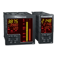
Load
Current
transformer
D) CURRENT TRANSFORMER INPUT
Fig. 10 CURRENT TRANSFORMER INPUT WIRING
This input allows you to measure and display the current running
in the load, driven by a time proportional control output, during
the ON and OFF periods of the output cycle time. By this feature
it is also available the "Output failure detection" function (see
page 66).
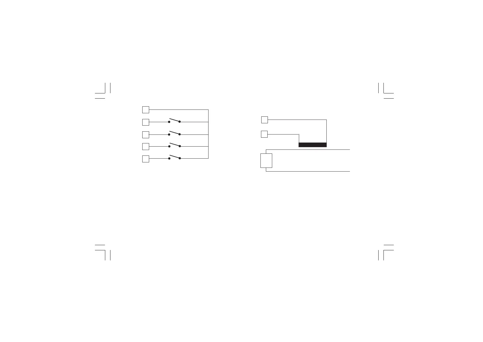
Fig. 9.c - LOGIC INPUTS IN 5, 6, 7 and 8 WIRING
NOTES:
1) Do not run logic input wiring together with power cables.
2) Use an external dry contact capable of switching 0.5 mA,
5 V DC.
3) The instrument needs 110 ms to recognize a contact status
variation.
4) The logic inputs are NOT isolated by the measuring input. A
double or reinforced insulation between instrument output and
power supply must be assured by the external element.
47
48
IN 6
IN 7
45
46
IN 5
49
IN 8
Xkc-1-C0.P65 5/29/02, 11:59 AM10