16
The two relay output must be interlocked (see chapter
"Preliminary hardware setting" paragraph "Out 3 and 4
selection").
NOTES:
1) Before connecting the instrument to the power line, make sure
that line voltage and the load current are in accordance with the
contact rating (3A/250V AC on resistive load).
2) To avoid electric shock, connect power line at the end of the
wiring procedure.
3) For servomotor connections use No 16 AWG or larger wires
rated for at last 75 °C.
4) Use copper conductors only.
5) Don’t run input wires together with power cables.
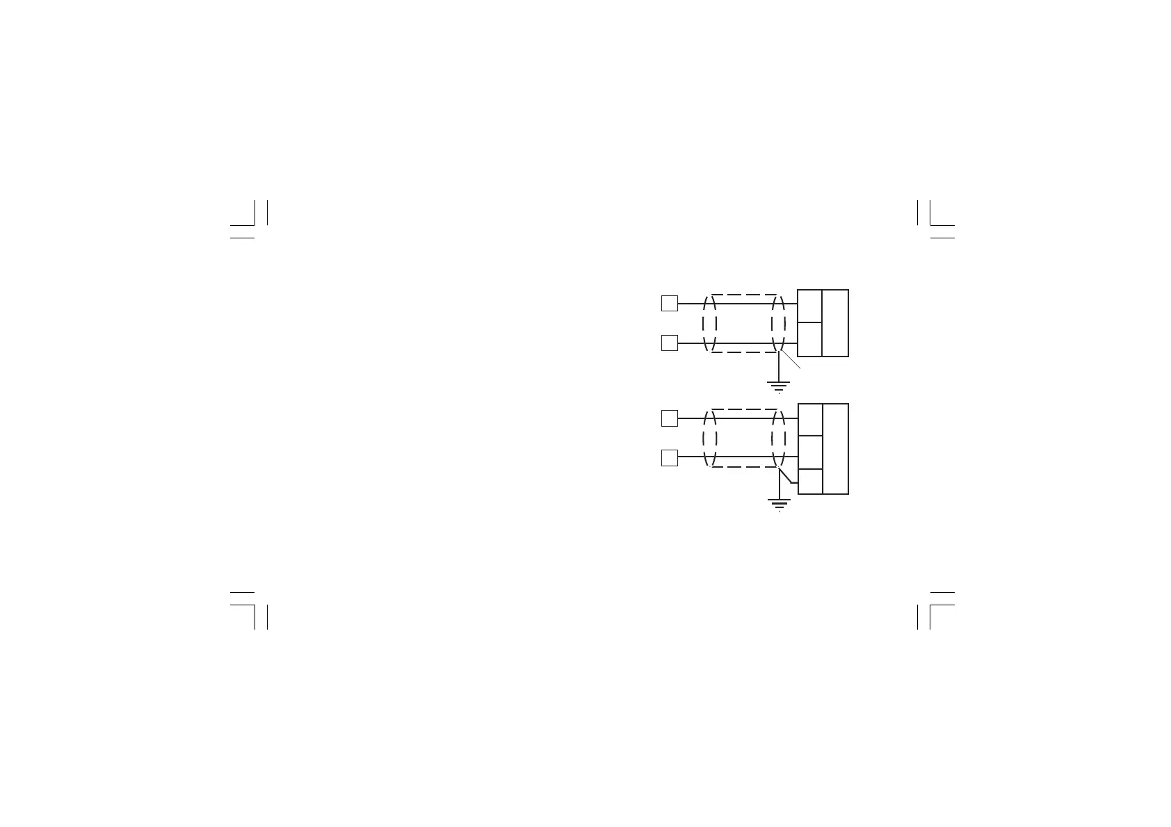
6) For feedback potentiometer, use shielded cable with the shield
connected to the earth at one point only.
7) The relay outputs are protected by varistor against inductive
load with inductive component up to 0.5 A.
E.5) ANALOG OUTPUTS
Fig. 16.A OUTPUT 5 WIRING
+
_
Shield
_
+
17
+
_
G
16
17
16
OUT 5
OUT 5
20 mA20 mA
+
_
Xkc-1-C0.P65 5/29/02, 11:59 AM16