13
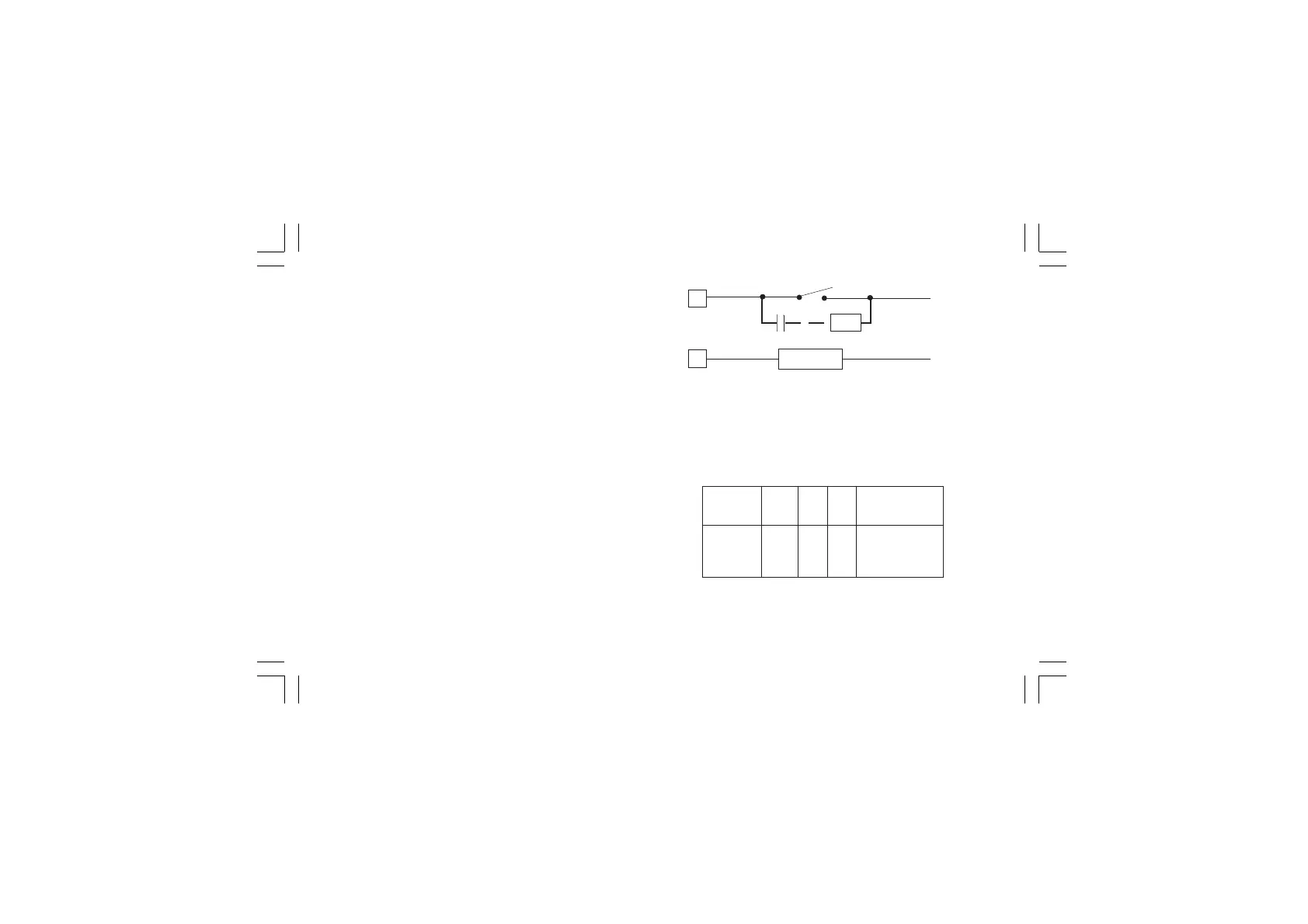
Fig. 12 EXTERNAL SWITCH IN SERIES WITH THE INTER-
NAL CONTACT
In this case it is recommended to install an additional RC
network across the external contact as show in Fig. 12
The value of capacitor (C) and resistor (R) are shown in the
following table.
Anyway the cable involved in relay output wiring must be as far
away as possible from input or communication cables.
NOTES 1) To avoid electrical shock, connect power line at
the end of the wiring procedure.
2) For power connections use No 16 AWG or larger
wires rated for at last 75 °C.
3) Use copper conductors only.
4) Don’t run input wires together with power cables.
All relay contacts are protected by varistor against inductive load
with inductive component up to 0.5 A.
The following recommendations avoid serious problems which
may occur, when using relay output for driving inductive loads.
INDUCTIVE LOADS
High voltage transients may occur switching inductive loads.
Through the internal contacts these transients may introduce
disturbances which can affect the performance of the instru-
ment.
For all the outputs, the internal protection (varistor) assures a
correct protection up to 0.5 A of inductive component.
The same problem may occur when a switch is used in series
with the internal contacts as shown in Fig. 12.
R
C
LOAD
LINE
LOAD
(mA)
<40 mA
<150 mA
<0.5 A
C
(mF)
0.047
0.1
0.33
R
(W)
100
22
47
P.
(W)
1/2
2
2
OPERATING
VOLTAGE
260 V AC
260 V AC
260 V AC
Xkc-1-C0.P65 5/29/02, 11:59 AM13