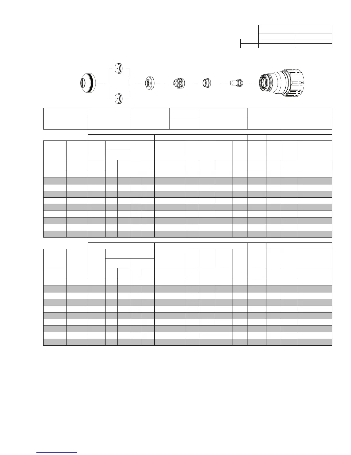
Manual 0560956430 187 TORCH DATA 100i-400i
Stainless Steel
Flow Rates (SLPM / SCFH)
300A Bevel Cut
H35 N₂
Preow
- / - 74 / 157
H35 Plasma / N₂ Shield
Culow
44 / 93 51 / 108
Electrode
Shield Retainer
Tip
Art # A-08567_AB
Plasma Gas
Distributor
Cartridge Assembly
This Art Is For Reference ONLY
Shield Cap
Shield Gas
Distributor
Shield Retainer Shield Cap
Shield Gas
Distributor
Tip Plasma Gas Distributor Electrode Cartridge
0559211211
< 1” / 0559210151
≥ 1” / 0559210153
0559210082 0559210130 0559210061 0559210111 0559211300
Manual Gas Control Advanced Torch Height Control (THC) Basic THC CNC Control
Eecve
Material
Thickness
Min.
Clearance
Pre Flow
Pressure
(N₂)
Cut Flow Rates / Pressures
Eecve Cut
Height
THC
Pierce
Delay
Pierce
Ignion
Height
Elevaon
Height
Control
Delay
Pierce
Height
without
Elevaon
Travel
Speed
CNC
Moon
Delay
Max Kerf Width
@ Rec. Speed
Plasma (H35) Shield (N₂)
inch (in) (psi) Ball (psi) Ball (psi) (in) (sec) (in) (in) (sec) (in) (ipm) (sec) (in)
0.375 0.080 20 120 100 NA 120 0.350 - 0.550 0.2 0.250 0.200 0.4 0.350 85 0.2 0.175
0.500 0.080 20 120 100 NA 120 0.350 - 0.550 0.4 0.250 0.200 0.2 0.350 75 0.4 0.193
0.625 0.080 20 120 100 NA 90 0.350 - 0.550 0.7 0.275 0.250 0.2 0.375 65 0.5 0.197
0.750 0.080 20 120 100 NA 90 0.350 - 0.550 0.9 0.275 0.250 0.2 0.375 55 0.6 0.195
0.875 0.080 20 120 100 NA 90 0.350 - 0.550 1.1 0.275 0.250 0.2 0.375 45 0.7 0.210
1.000 0.080 20 120 100 NA 120 0.350 - 0.550 1.6 0.400 0.400 0.2 0.500 35 0.9 0.226
1.250 0.080 20 120 100 NA 120 0.400 - 0.550 1.8 0.400 0.400 0.2 0.700 30 1.0 0.203
1.500 0.080 20 120 100 NA 120 0.400 - 0.550 0.5 Edge Start 0.2 Edge 25 0.5 0.220
1.750 0.080 20 120 100 NA 120 0.400 - 0.550 0.5 Edge Start 0.2 Edge 21 0.5 0.229
2.000 0.080 20 120 100 NA 120 0.400 - 0.550 0.5 Edge Start 0.2 Edge 17 0.5 0.237
Manual Gas Control Advanced Torch Height Control (THC) Basic THC CNC Control
Eecve
Material
Thickness
Min.
Clearance
Pre Flow
Pressure
(N₂)
Cut Flow Rates / Pressures
Eecve Cut
Height
THC
Pierce
Delay
Pierce
Ignion
Height
Elevaon
Height
Control
Delay
Pierce
Height
without
Elevaon
Travel
Speed
CNC
Moon
Delay
Max Kerf Width
@ Rec. Speed
Plasma (H35) Shield (N₂)
(mm) (mm) (Bar) Ball (Bar) Ball (Bar) (mm) (sec) (mm) (mm) (sec) (mm)
(mm/
min)
(sec) (mm)
10 2.0 1.4 120 6.9 NA 8.3 8.9 - 14 0.2 6.4 5.1 0.4 8.9 2120 0.2 4.5
12 2.0 1.4 120 6.9 NA 8.3 8.9 - 14 0.4 6.4 5.1 0.2 8.9 1960 0.4 4.8
15 2.0 1.4 120 6.9 NA 6.8 8.9 - 14 0.6 6.8 6.0 0.2 9.3 1720 0.5 5.0
20 2.0 1.4 120 6.9 NA 6.2 8.9 - 14 1.0 7.0 6.4 0.2 9.5 1320 0.6 5.1
25 2.0 1.4 120 6.9 NA 8.0 8.9 - 14 1.5 9.8 9.7 0.2 12.3 920 0.9 5.7
30 2.0 1.4 120 6.9 NA 8.3 9.8 - 14 1.7 10.2 10.2 0.2 16.4 800 1.0 5.3
35 2.0 1.4 120 6.9 NA 8.3 10.8 - 14 1.9 10.2 10.2 0.2 20.4 700 1.1 4.9
40 2.0 1.4 120 6.9 NA 8.3 10.2 - 14 0.5 Edge Start 0.2 Edge 600 0.5 5.7
45 2.0 1.4 120 6.9 NA 8.3 10.2 - 14 0.5 Edge Start 0.2 Edge 520 0.5 5.8
50 2.0 1.4 120 6.9 NA 8.3 10.2 - 14 0.5 Edge Start 0.2 Edge 440 0.5 6.0
BOLD TYPE indicates maximum piercing parameters. BOLD ITALIC indicates edge starts only.
 Loading...