VIP-X System Manual
Revision 1.0 VIP-X - 23
4. SYSTEM COMMUNICATION
The following section details the VIP-X system communication interconnectivity, including networking
connections, X-LINK connections and video.
4.1. NETWORK CONNECTIVITY
4.1.1. Xenon Based VIP-X Solution
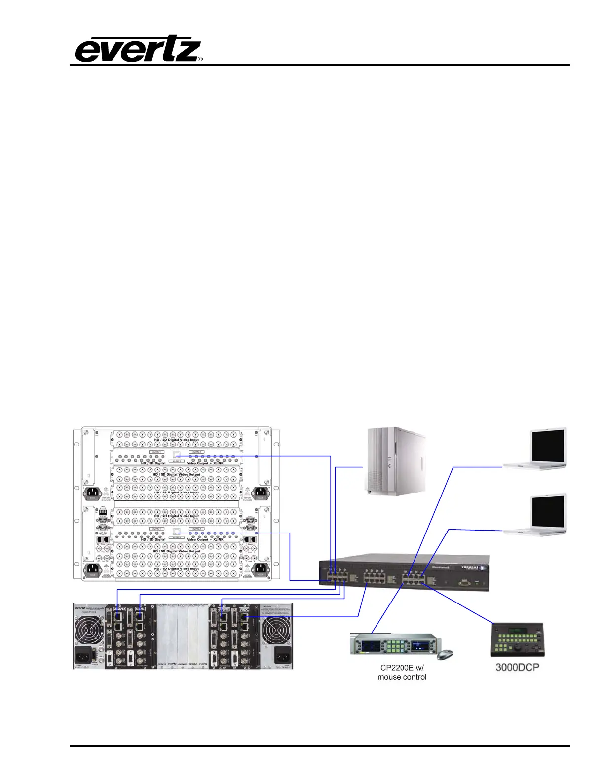
Figure 4-1 below, details the Ethernet connection points in the system. Evertz recommends that a
proper Ethernet 10/100 base Ethernet switch or greater be used to support the systems network. Also,
Evertz highly recommends the VIP-X system be operated on its own VLAN where possible.
Each Xenon enabled output card has a separate Ethernet port which is used to control the X-LINK
outputs for that card. Each 7767VIPX module has its own Ethernet port which is used to control the
associated 7767VIPX device. Ethernet 2 on the 7767VIPX device must be used for proper
communication.
The “System Manager” server computer must also be connected to the same network as the hardware
for the purpose of managing the system. Use the computer’s appropriate Ethernet port for this
connectivity.
All Ethernet based control panels must be on the same network as the VIP-X system in order to control
the system. All control panels, and software clients connect via TCP/IP to the System Manager
software, which relays the information to the hardware as appropriate.
Maestro Client
Maestro Client
CP22OE w/
Mouse Control
3000DCP
VIP-X System
Manager
10/100/1000 Ethernet Switch
Figure 4-1: Network Connectivity Diagram – Xenon Router