VIP-X System Manual
VIP-X - 32 Revision 1.0
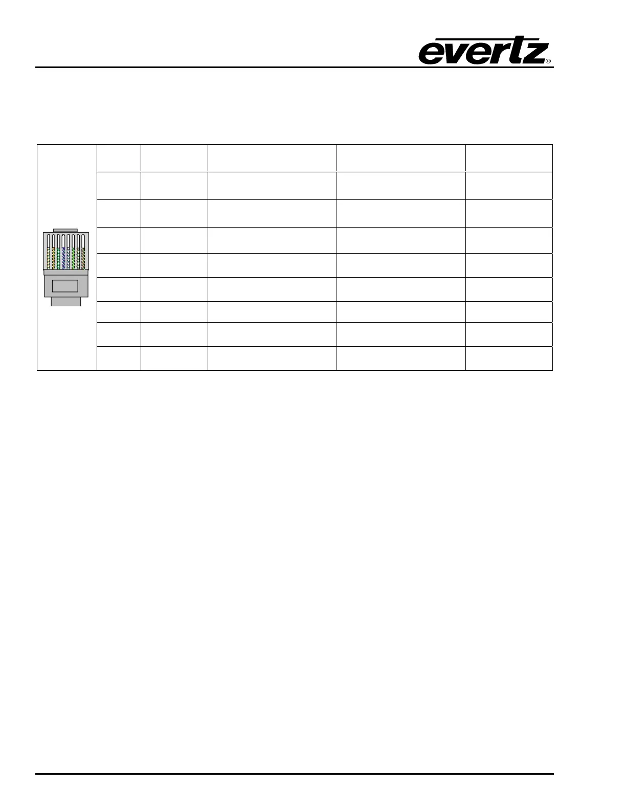
The straight-through RJ-45 cable can be purchased or can be constructed using the pinout information
in Table 5-3. A colour code wiring information is provided in Table 5-3 for the current RJ-45 standards
(AT&T 258A or EIA/TIA 258B colour coding shown). Also refer to the notes following the table for
additional wiring guide information.
Pin # Signal EIA/TIA 568A
AT&T 258A or
EIA/TIA 568B
10BaseT
or 100BaseT
1
Transmit + White/Green White/Orange X
2
Transmit – Green/White or White Orange/White or Orange X
3
Receive + White/Orange White/Green X
4
N/A Blue/White or Blue Blue/White or Blue
Not used
(required)
5
N/A White/Blue White/Blue
Not used
(required)
6
Receive – Orange/White or Orange Green/White or Green X
7
N/A White/Brown White/Brown
Not used
(required)
Pin
1
8
N/A Brown/White or Brown Brown/White or Brown
Not used
(required)
Table 5-3: Standard RJ45 Wiring Colour Codes
Note the following cabling information for this wiring guide:
• Only two pairs of wires are used in the 8-pin RJ-45 connector to carry Ethernet signals
• Even though pins 4, 5, 7 and 8 are not used, it is mandatory that they be present in the cable
• 10BaseT and 100BaseT use the same pins; a crossover cable made for one will also work with the
other
• Pairs may be solid colours and not have a stripe
• Category 5 cables must use Category 5 rated connectors
The maximum cable run between the 7767VIPX8x2 or 7767VIPX16x2 and the supporting hub is 300 ft
(90 m). The maximum combined cable run between any two end points (i.e. 7767VIPX8x2 and
PC/laptop via network hub) is 675 feet (205 m).