VIP-X System Manual
Revision 1.0 VIP-X - 31
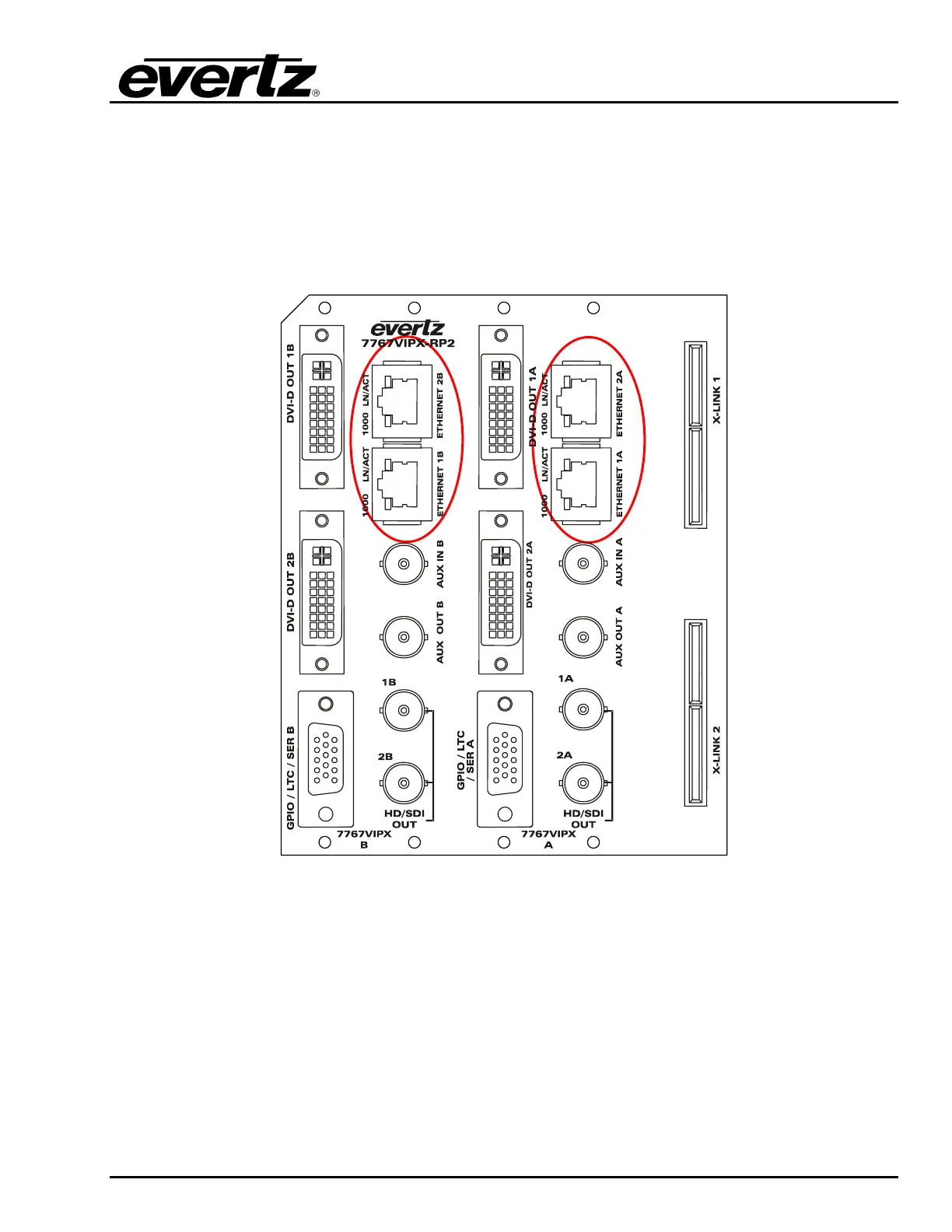
5.6. ETHERNET NETWORK CONNECTIONS
ETHERNET1 / 2: These RJ-45 connectors are Ethernet ports which facilitate control via VistaLINK
®
PRO or Maestro software. It is also used for FTP firmware upgrades. The VIP module
comes delivered from the factory with Ethernet 2 as the default active port; Ethernet 1 is
disabled and is not used at this time. Since the 7767VIPX-RP2 rear panel
accommodates two VIP-X modules, the rear plate has Ethernet ports 1A and 2A for the
first VIP-X module and 1B and 2B for the second VIP-X module.
Figure 5-7: Rear Plate – Ethernet Ports
The 7767VIPX8x2and 7767VIPX16x2 are designed to be used with either 10Base-T (10 Mbps) or
100Base-TX (100 Mbps) also known as Fast Ethernet, twisted pair Ethernet cabling systems. When
connecting for 10Base-T systems, category 3, 4, or 5 UTP cable as well as EIA/TIA – 568 100Ω STP
cable may be used. When connecting for 100Base-TX systems, category 5 UTP cable is required.
Make the network connection by plugging one end of a “straight through” cable into the RJ-45
receptacle of the 7767VIPX8x2 or 7767VIPX16x2 and the other end into a port of the supporting hub. If
the user is connecting the VIPX card directly to an Ethernet port on a computer the user will have to
use a “crossover” cable.