VIP-X System Manual
Revision 1.0 VIP-X - 27
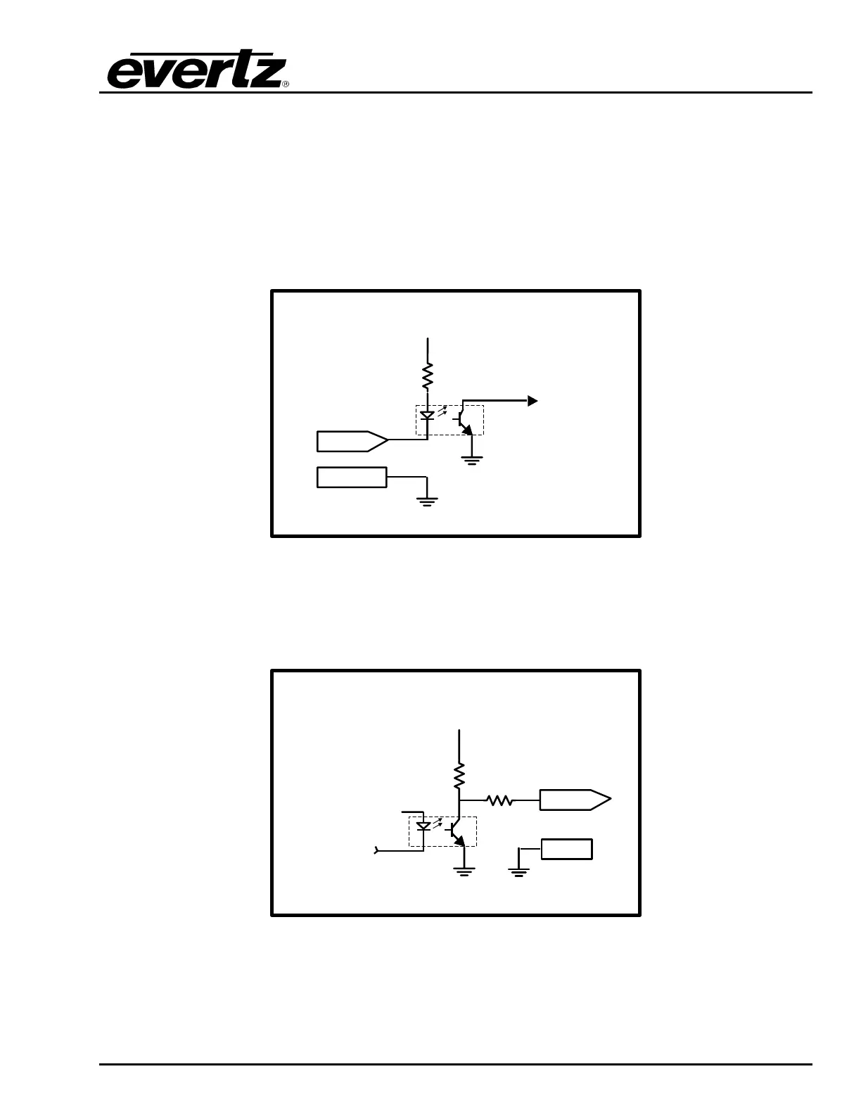
5.4. GENERAL PURPOSE INPUTS AND OUTPUTS
GPI interfacing with the 7767VIPX is possible through 4 general purpose inputs (pins 10, 11, 12, 13)
and 2 general purpose outputs (pins 4, 9) available on the HD-15 connector on the rear plate of the
module. The GPIs are active low with internal pull-up resistors (4.7k Ohms) to +5 V. To make an input
active, lower the signal to near ground potential (i.e. connect to shell or chassis ground). This can be
done with a switch, relay, TTL drive, GPO output, or using another similar method. Figure 5-2 shows
the input circuit for the general-purpose inputs. Figure 5-4 shows an example of how to interface the
VIP GPI inputs to higher voltage systems.
GND
To Internal
Circuit
4.7 k
Ω
GPI
+ 5 Volts
Figure 5-2: GPI Input Circuitry
The GPOs are active low with internal pull-up (10kΩ) resistors to +5 V. When the output goes low, it is
able to sink up to 10 mA; when the output goes high, the signal will go high (+5 V). Do not draw more
than 100µA from the output. Figure 5-3 shows the circuit for the general-purpose output:
From Internal
Circuit
10k
Ω
+ 5 Volts
GND
GPO
10
Ω
Figure 5-3: GPO Output Circuitry