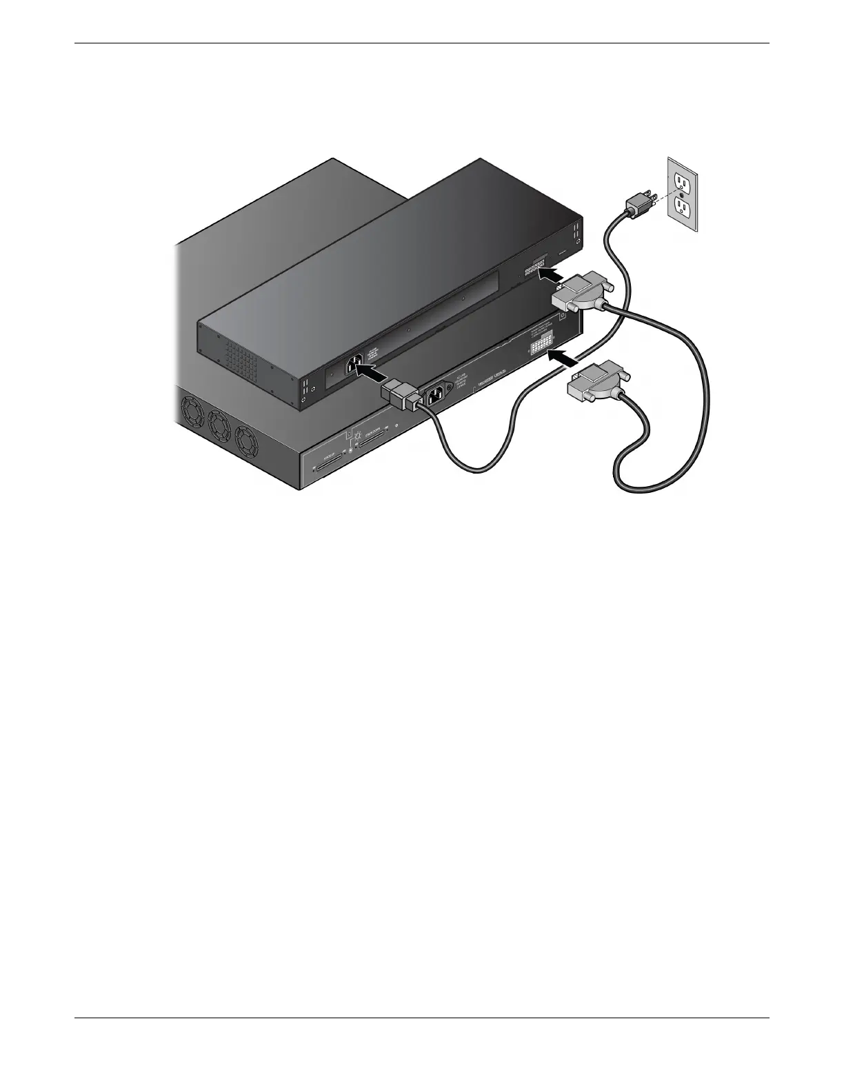
2. Disconnect the RPS cable from the rear panel of the RPS and the rear panel of the
switch.
Figure 62: RPS cable and AC Power Cord Connection
The AC power LED on the rear of the RPS turns off to indicate that the power to the
RPS has been disconnected.
Disconnect the RPS Cable and the AC Power Cord Remove and Replace Components
88 ExtremeSwitching 5320 Series Hardware Installation Guide

 Loading...

