SMP 111 • Installation 11
Installation
This section provides information on:
• Mounting the SMP111
• Rear Panel Overview
• SMP111 Rear Panel Reset
Mounting the SMP111
The SMP111 is housed in a 1U high, half rack width, two piece metal enclosure that can
sit on a table with the provided rubber feet or can be mounted using the attached rack
mounts. Select a suitable mounting location, (see Mounting the SMP111 on page90)
then choose an appropriate mounting option.
Before connecting the SMP111, turn off all devices that are to be connected.
Make all external device connections to the SMP before applying power.
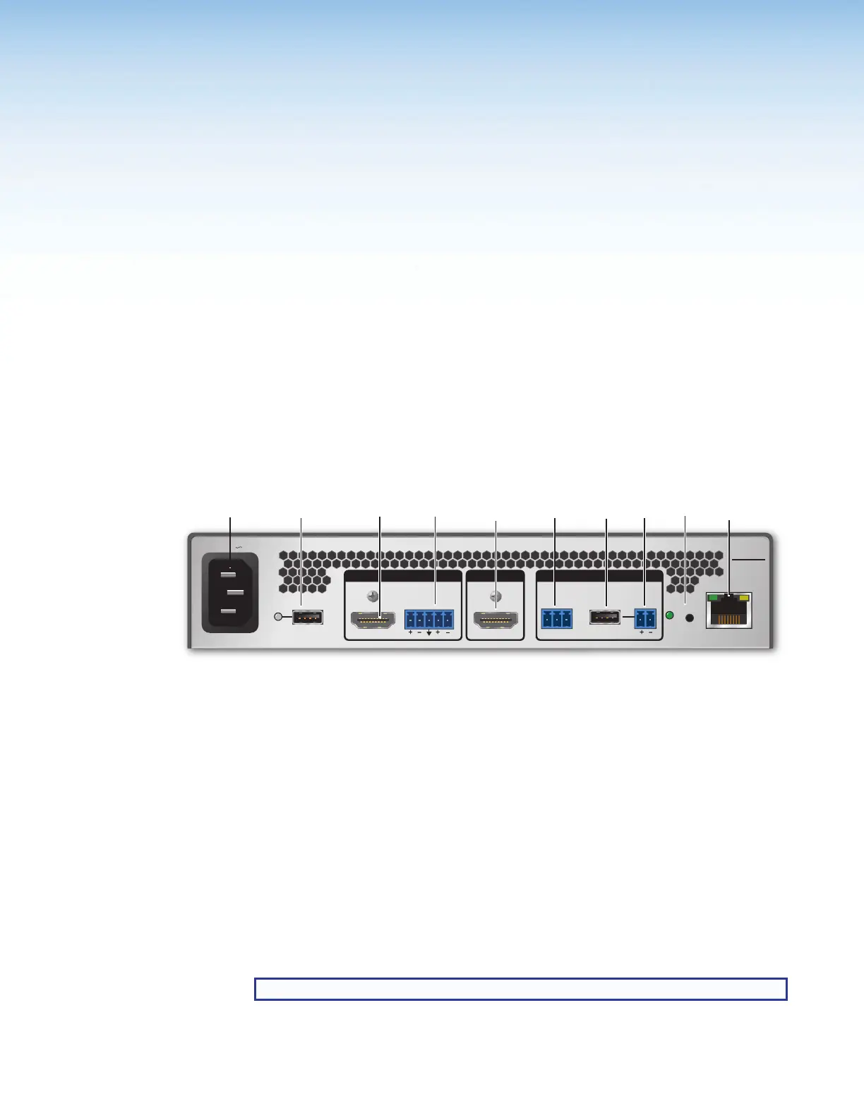
Rear Panel Overview
RxTx G
RS-232 CONTROL
RESET
+12V
1.0A MAX
INPUTS OUTPUT REMOTE
SMP 111
100-240V 0.7A
50-60 Hz
LAN
USB STORAGE
HDMI HDMI
L
AUDIO
LINE R
AB CD EFGH IJ
Figure 3. SMP111 Rear Panel
A
100-240 VAC IEC connector for power input
F
3.5 mm, 3-pole captive screw connector for Simple
Instruction Set (SIS) control over RS-232
B
USB type A receptacle for external storage device
and activity LED
G
USB type A receptacle for remote control panel
RCP 101
C
HDMI input (Input)
H
12V, 2-pole captive screw external power output to
RCP 101
D
3.5 mm, 5-pole captive screw connector for analog
stereo audio input
I
Reset button and LED
E
HDMI preview output
J
RJ-45 Ethernet connector for LAN connection
Power Connection
A
100-240 VAC power input — Connect the provided IEC cord. Verify the front panel
buttons and LCD illuminate (see Front Panel Features on page16).
NOTE: Make all external device connections to the SMP before applying power.
figure 3