Chapter 6 Fastening Operation
PAGE 6-43
System Parameters (controller Information 1)
D-No.000 Torque Unit
All fastening parameters within the Controller will have the same torque unit.
D-No. 001 Software Version Cannot be changed.
This is the software version of the controller.
D-No. 002 Amplifier Version Cannot be changed.
This is the amplifier version.
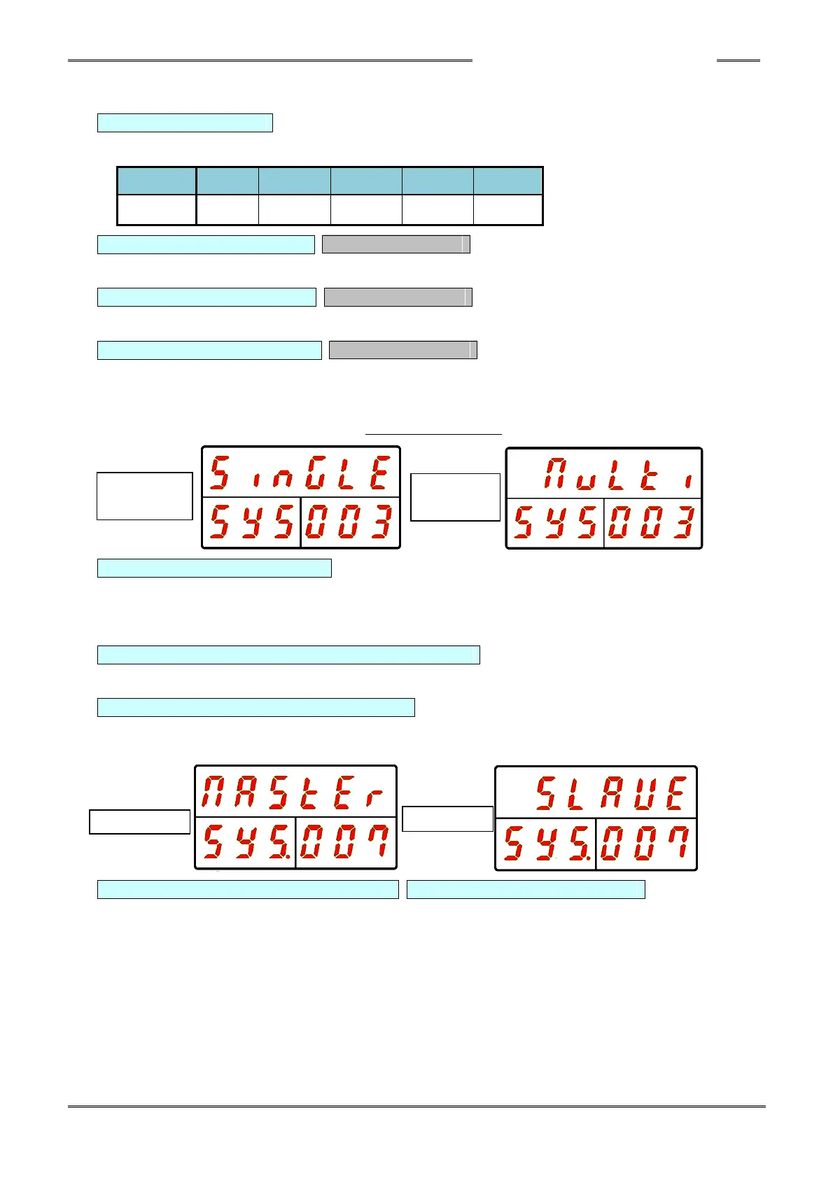
D-No. 003 System Indication Cannot be changed.
Indicates whether the controller is a multi system or a single system configuration.
This is also used to change between the multi system and the single system.
The handheld tool operates only in the single system setting.
D-No. 004 External Gear Ratio Setting range: 0.300 ~ 3.000, standard setting: 1.000
Used to adjust the gear ratio when an external head (that has a gear ratio other than 1:1) is connected
to the output shaft of the tool. Do not use a value other than the standard setting (1.000) unless an
external offset gear is attached.
D-No.005 / 006 For adjustment by the manufacturer
Not used.
D-No. 007 Communication Axis Indication
This indicates whether the controller is the MASTER spindle for (PC) communication
and I/O (PLC) communication or is a SLAVE Spindle
D-No. 008 Axis Cycle Count (×1 million) D-No. 009 Axis Cycle Count (×1)
Indicates the number of fastening cycles the controller has performed.
* When the count is less than 1 million, [------] is indicated for D-No. 008.