Chapter 9 Fieldbus I/O Interfaces
PAGE 9-12
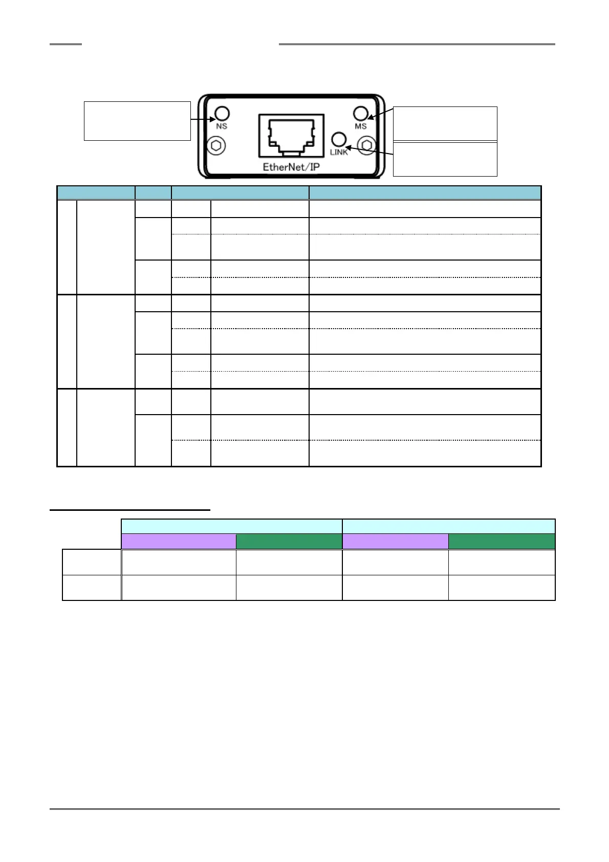
● List of LED Indications
The module LEDs indicate the node status of the AFC3000 Ethernet-I/P System and the network state.
9-2-3 I/O Signal Specifications
Offline, No power or no IP address
Online, One or more connections established
Communication not
established
online, connection is not establishe
Fatal error has occurred. / Conflicting IP address.
One or more connection timeout has occurred
Controlled by a scanner in RUN state -
Communication not
established
Incomplete / wrong configuration or scanner in idle
state
Major Fault -A critical error has occurred.
A recoverable error has occurred.
ETHERNET link is not established and
communication is not performed.
ETHERNET link is established but not
communicating
ETHERNET link is established and communication
is in progress.