Chapter 9 Fieldbus I/O Interfaces
PAGE 9-32
9-3-6 System Area PLC Handshake
Enabling the CC-Link connection to the PLC
PLC Ladder logic is required to enable the CC-Link communication link. The logic must address the enable bit
(Initial Data Processing Request) of which the address changes based on the size setting used. The last 16 bits
of both the Inputs and outputs (no matter what size is configured) is the CCLINK system setting area and this is
where the link must be enabled.
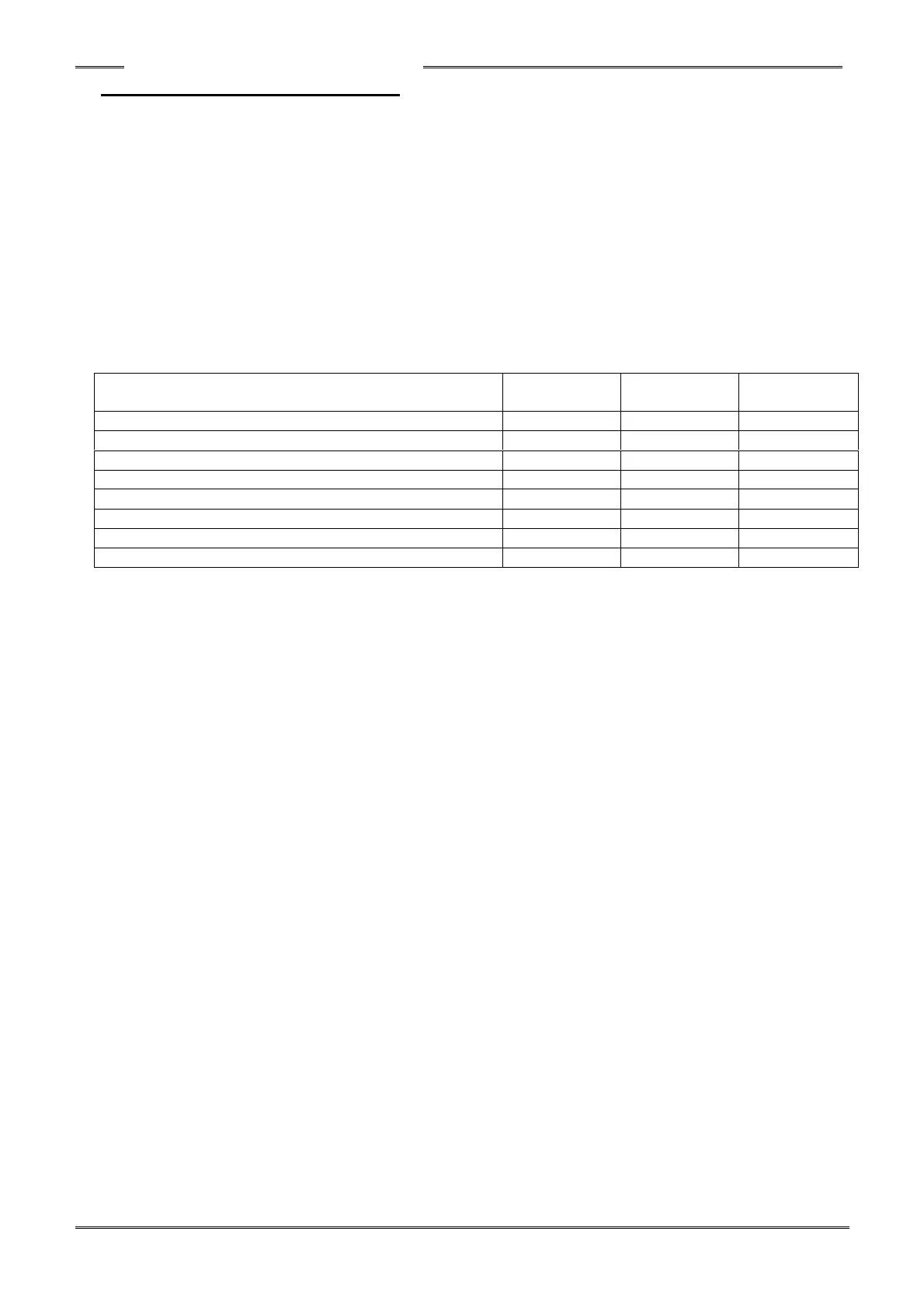
Below is an example of CC-Link configuration settings made by GX Developer software and how memory is allocated. This
configuration has 3 sets of HFC3000 controllers connected with 4 occupied stations / 8 extended cyclic cycles. (I/O 896 Points,
Message 72 Words)
In the case of the first HFC3000 System (1) (shown in the table above), the PLC program is set so that when the
888th (378h) bit (“Initial Data Processing Request”) in the (CC-Link Reserved) system area (X area) is turned “ON”,
the output at the 888th (378h) bit (“Initial Data Processing Complete”) of the system area (Y area) is set “ON”.
(Note: See pages 8 & 14 for CCLINK handshaking signal location)
Since the X/Y starting address of (System 1) is configured to start at X100 and Y100, this must be added to the
addresses and therefore (100h+378h) 478h is specified for the X area and the Y area as shown in the PLC Logic
diagram below to enable Station 1’s link.
For Station 2’s link, the starting address (X/Y480) is added to the 888
th
(378h) bit for that station which is address
(480h + 378h) X/Y7F8.
For Station 3’s link, the starting address (X/Y800) is added to the 888
th
(378h) bit for that station which is address
X/YB78.
PLC Logic example that would be required to enable the CC-Link in the three systems listed above