Chapter 3 Sysytem Description
PAGE 3-3
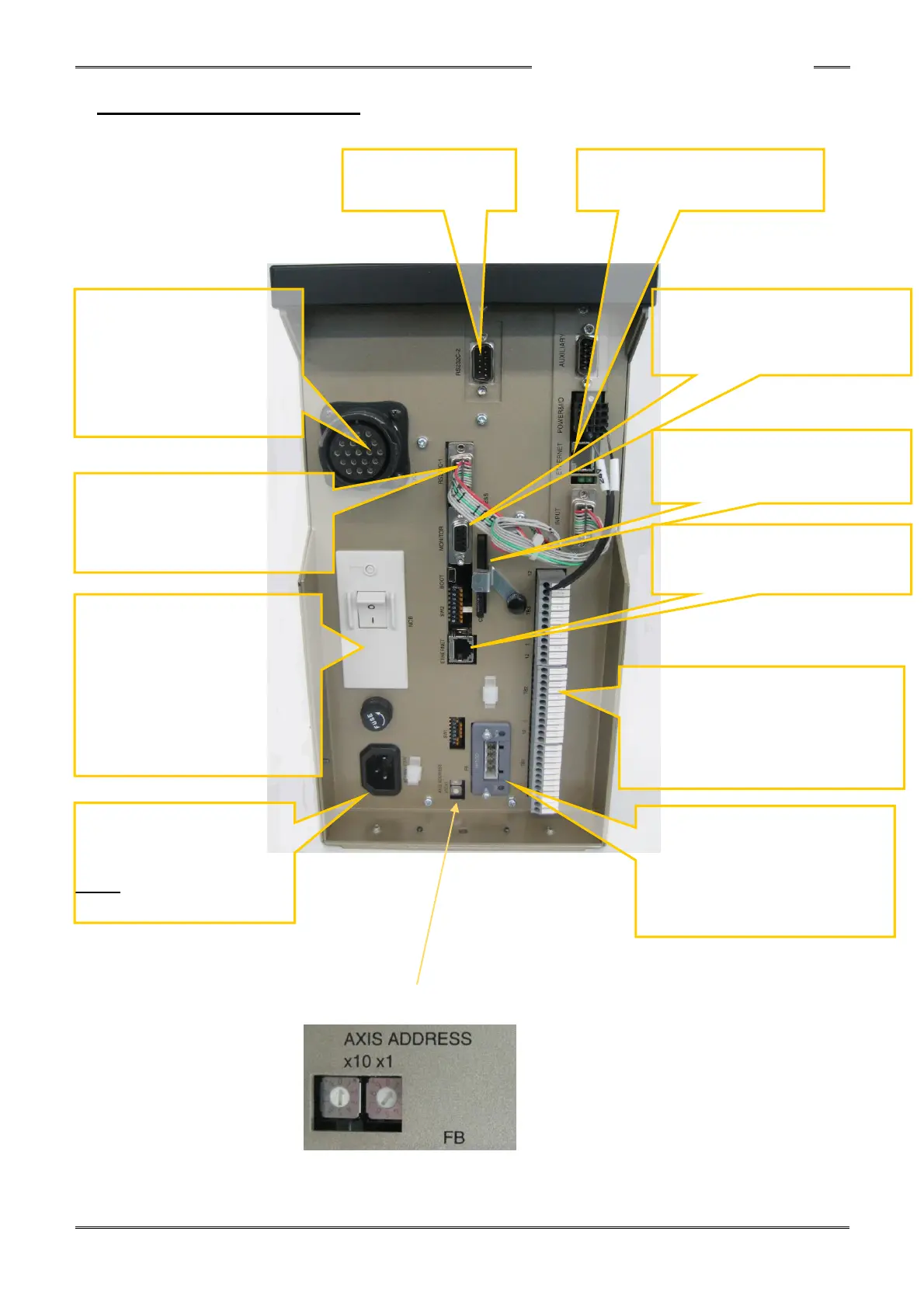
3-1-2 Controller Bottom Panel
Note : * FIELDBUS, CF card, RS232C-2 and Data Report Ethernet are optional.
AXIS ADDRESS rotary switches (Set a “01” – Set “x10” to “0” and “x1” to “1” - Do not change)
MONITOR
Connector for torque and angle
analog monitor output connection.
(PAGE 4-18)
RS232C-1
Connector for output of fastening
result data.
Can be connected to a PLC, printer,
PC, etc. (Section 4-7).
100~240V AC
Primary power input connector
Operates on a single-phase
50/60Hz power source.
MUST provide secure
grounding.
TB1,2,3
Connector for input/output signal
connection.
Refer to separate section for signal
details and precautions (Sec. 4-5).
Ground Fault Breaker
When a ground leakage
occurs in the controller, cable,
or tool, this breaker trips
instantaneously to secure
safety from the ground fault
I…ON
O…OFF
TOOL
Connector for tool cable
connection.
Twist lock type connector.
Can be connected and
disconnected by twisting 90
degrees.
FIELDBUS Interface
Communication interface for PLC
I/O signals using this optional
interface (DeviceNet, Ethernet I/P,
CC-Link, etc., in accordance with
user specifications (Section 9).
*RS232C-2
For ID data input
*CF Card
Stores fastening result data and
curve data in Compact Flash.
*Optional DATA REPORT
ETHERNET
ETHERNET
For HFC Software connection
PC