Chapter 4 Installation and Wiring
PAGE 4-8
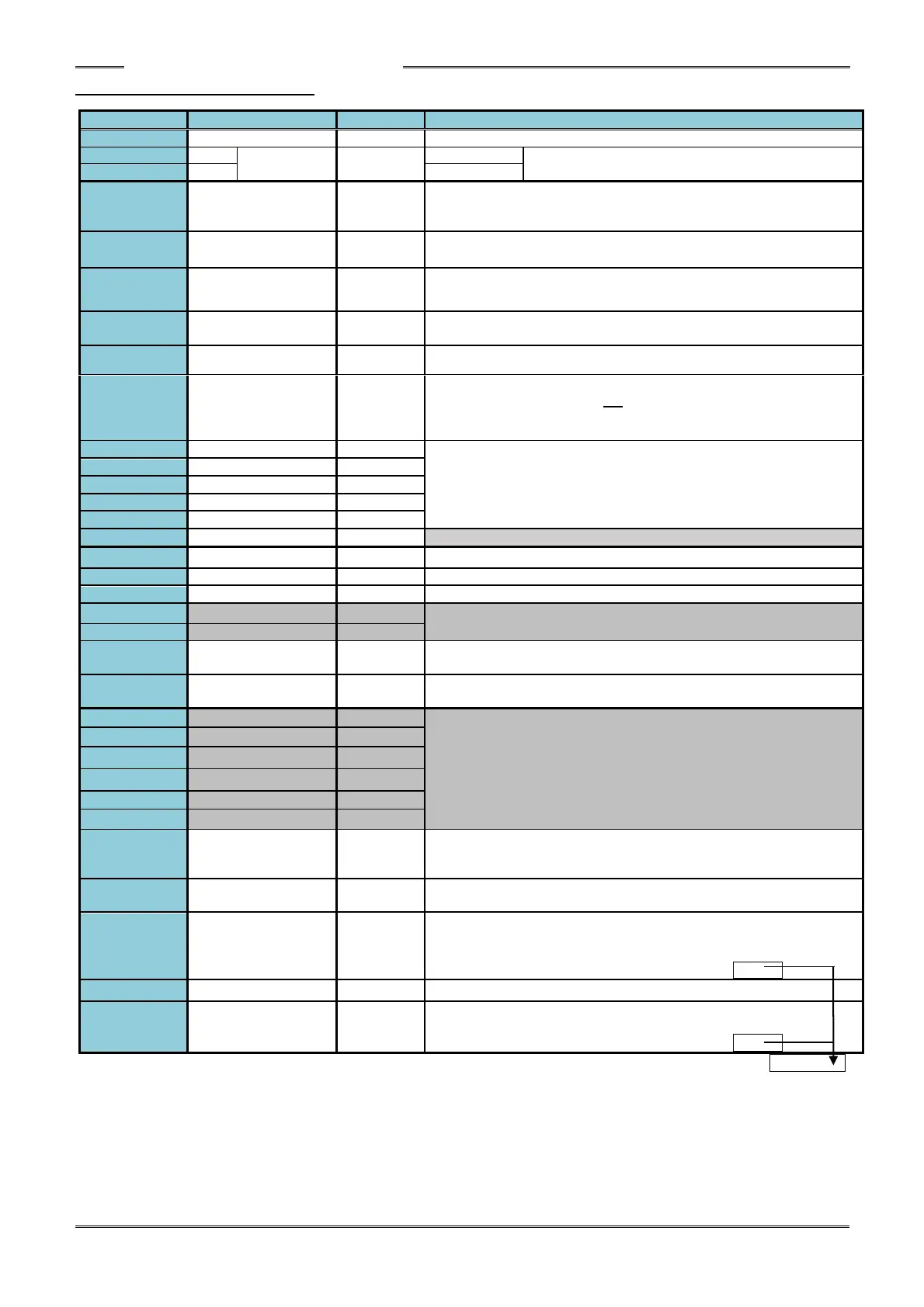
4-5-1 Controller I/O Signals
System parameter: SYS.033[xxx1xx] 0: 300ms/1: 800ms pulse length
Description of Function/Usage
Common input signal (bipolar)
When using this power supply, keep wiring away from
electrical noise exposure.
The fastening process is stopped when this signal is set to “OFF.”
Selection between A contact and B contact type is possible.
System parameter: SYS.033[xx1xxx] 0: A contact/1: B contact
The fastening process is stopped and the fastening judgment of the
controller is cleared when set “ON.” (ID data is cleared as well.)
The tool rotates in reverse direction while “ON” and at the speed in
accordance with the selected WORK No. (Parameter)
When “ON”, the fastening process is started in accordance with the
selected WORK No. (“Deadman” specification).
The controller is put in the BYPASS (PROGRAM) mode when “ON”.
When set “ON”, the self-check of the torque transducer (Zero Level /
Cal level voltage check) will not be performed (normally before the
start of the fastening operation - the start of tool rotation can be
shortened by approx. 60msec).
The WORK SELECT BIT 0 ~4 select signals enable selection
among parameter Nos. 1 ~ 32 by a (Binary) combination of the 5 pin
Nos. (See Work Select table further below)
Bank select input signal (changes output signal definition)
Common output signal (bipolar)
Cycle counter (ACCEPT count) reset signal
Output definition depends on status of Bank Select Input (TB1-12)
(See next page for output definition)
The Work Select Bit 5 enables selection of parameters 33-64 in
combination with Work Select Bits 0-4 (Firmware Ver. 1.301 or later)
Thw Work number selection by ID data input is enabled when ON.
(Firmware Ver. 1.301 or later)
Output definition depends on status of Bank Select Input (TB1-12)
(See next page for output definition)
Turns ON when manually starting the reversed operation.
Turns OFF when the next fastening starts or turns OFF at RESET,
PROGRAM. (Relay contact-1)
Performs a duplication of the controller buzzer output of the REJECT
signal and Batch OK to external devices. (Relay contact-2)
BATCH OK (RY3-1)
[TOTAL OK]
Output when the fastening results are OK for the programmed number
of cycles when using batch counting function (relay contact-3).
Selection between pulse or constant output is possible.
System parameter: SYS.033[xxxx1x] 0: constant 1: pulse
Relay contact-1, 2, 3 common
QL OK (RY4-1)
[OK] (RY4-2)
OK output for QL Accept signal (relay contact) (Relay contact-4)
Selection between pulse and constant output is possible.
System parameter: SYS.033[xxxxx1] 0: constant 1: pulse