59
The cooling mixture is circulated by a
centrifu-
gal
pump
driven by the engine crankshaft with a
triangular belt.
Thermostatic valve
cover
is
fitted
with an
air-
bleed valve
to
be used when filling
the
cooling
system
or
when bad circulation
problems
arise.
In
the
lower
part
of
the
radiator there
is
fitted
a
temperature
sensitive switch 3
for
switching on
and
off
the
electric
fan when
the
temperature
exceeds 183
0
Fand when it is
below
167
0
F.
The
thermostatic
valve 2 begins
to
open when
the
mixture
temperature
reaches
176
0
.;..
185
0
F.
The
tank
1 takes care
of
changes
in
volume and
pressure
of
the
mixture which
occur
during en-
gine heating.
The
supplementary
expansion
tank
is
fitted
with a pressure
cap
set
to
12,8 p.s.i. via
which
the
cooling
system
should
be
filled.
Never
top
up
nor
fill
with
water
the
cooling
sy-
stem,
but
only
employ
the
specified
antifreeze
mixture.
Regularly
check
the
mixture level
in
the
header
tank
when
the
engine
is
cold.
La circolazione
eattivata da una
pompa
centri-
fuga
comandata
con cinghia trapezoidale
dall'albero motore.
II
corpo
valvola
termostatica
porta
nella parte
superiore una vite
per
10
sfogo dell'aria dal cir-
cuito
di
raffreddamento
allorquando
si
fa
il
riempimento
e si hanno problemi di cattiva cir-
colazione.
II
radiatore
porta
inferiormente
un
termocon-
tatto
3
per
I'inserimento
automatico
dell'elet-
troventilatore
quando
la
temperatura
della mi-
scela raggiunge 84
0
C e
ePer
il
disinserimento
quando
essa scende a 75
C.
La valvola del ter-
mostato
2
incomincia
ad aprirsi
quando
la
tem-
peratura della miscela raggiunge
80
..;..
85
0
C.
II
serbatoio
1
compensa
Ie
variazioni di volume
e di pressione della miscela
dovute
al riscalda-
mento
del motore: esso porta superiormente
un
bocchettone
con
tap
po
munito
di valvola ta-
rata a 0,9
kp/cm
2
attraverso
iI
quale
avviene
iI
riempimento
del
circuito
di
raffreddamento.
L'impianto
non
deve
essere
mai
rabboccato
0
riempito
con
acqua;
utilizzare
sola
mente
la
mi-
scela
di
antigelo
prescritta.
Controllare saltuariamente illivello della misce-
la nel serbatoio supplementare, esclusivamen-
te
a
motore
freddo.
6
~8
I
CD
,
,/
,
'.
<.
~
~'.'
..
7
<"fC~1(;""
.
.
•
,
I,'
"
I
I'
•
.»)
.---.
--
345
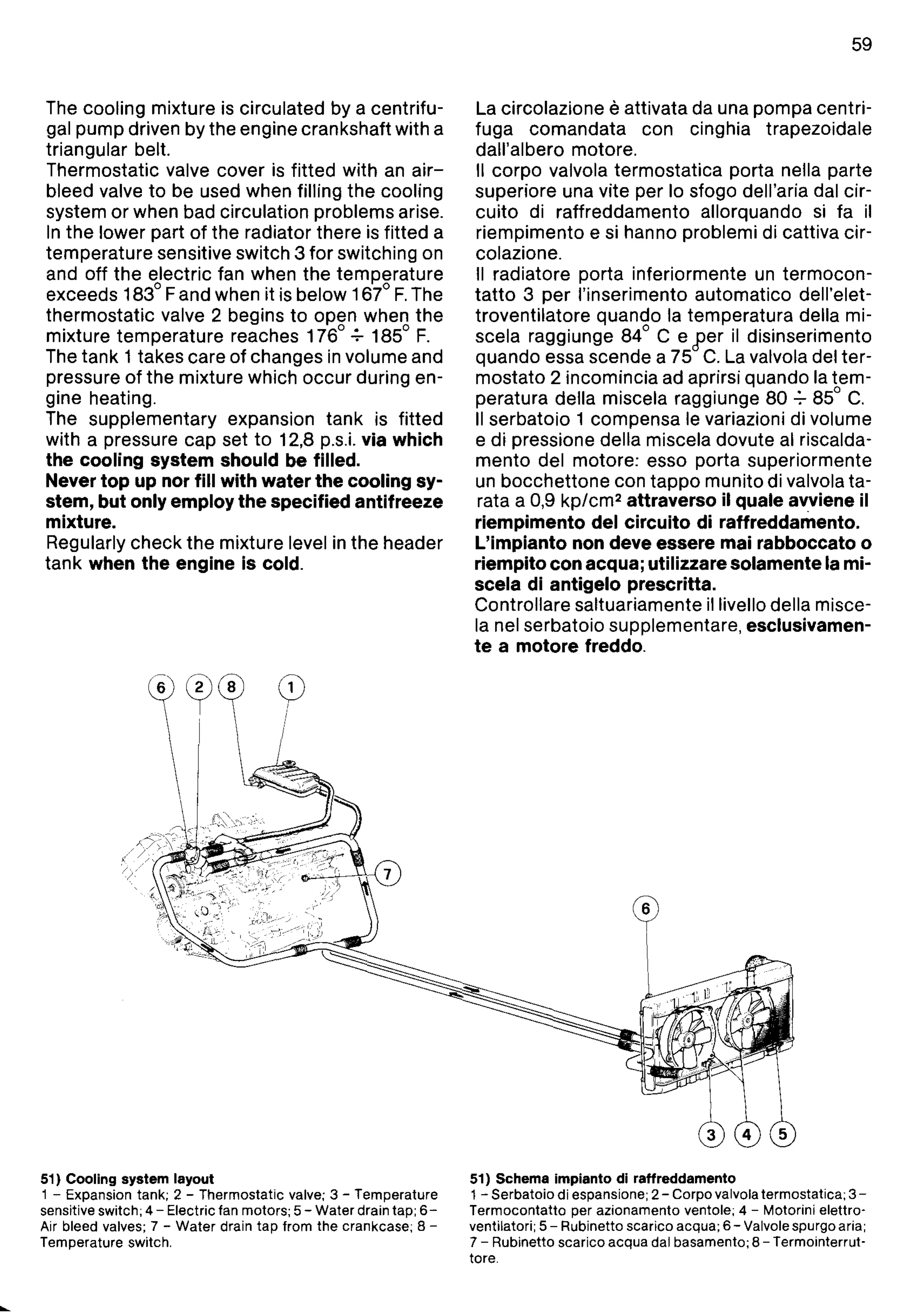
51) Cooling system layout
1 - Expansion tank; 2 - Thermostatic valve; 3 - Temperature
sensitive switch; 4 - Electric fan motors; 5 - Water drain tap;
6-
Air bleed valves; 7 -
Water
drain
tap
from the crankcase; 8 -
Temperature switch.
51) Schema impianto di raffreddamento
1 - Serbatoio di espansione; 2 - Corpo valvola termostatica;
3-
Termocontatto per azionamento vento
Ie;
4 - Motorini elettro-
ventilatori; 5 - Rubinetto scarico acqua; 6 - Valvole spurgo aria;
7 - Rublnetto scarico acqua dal basamento; 8 - Termointerrut-
tore.