take because
of
the vacuum caused by the en-
gine at the idling
as
well as
in
all
other
condi-
tions.
In
the pipe going into the air intake there
is
a fla-
me
arrestor.
Cleaning blow
by
system
75
pore e sono quindi aspirati dal
motore
attraver-
so la presa d'aria.
Sui
condotto
che va alia presa aria esistemato
un
rompifiamma.
Pulizia dell'impianto
lerrari
SERYICE
SEE
LUBRICATION AND MAINTENANCE
CHARTS PAGES
55
-
56
Hrrari
SIRYICE
VEDERE PIANI
01
LUBRIFICAZIONE E
MANUTENZIONE - PAG. 55 - 56
EVAPORATIVE EMISSION CONTROL
SYSTEM
The fuel evaporative control system is designed
to
prevent air pollution caused by evaporative
losses from the fuel system.
This
is
accomplished
by
a carbon storage sy-
stem which prevents the release into
the
at-
mosphere
of
fuel vapors fram the fuel tanks.
IMPIANTO CONTROLLO EMISSIONE
VAPORI
DI
BENZINA
II
sistema di contrallo delle emissioni per eva-
porazione
epragettato per prevenire I'inquina-
mento atmosferico da evaporazione dall'im-
pianto di alimentazione.
Cia e
ottenuto
tramite un appropriato sistema
che previene
10
scarico nell'atmosfera dei va-
pori dai serbatoi.
A
F
E
C
G
B
D
H
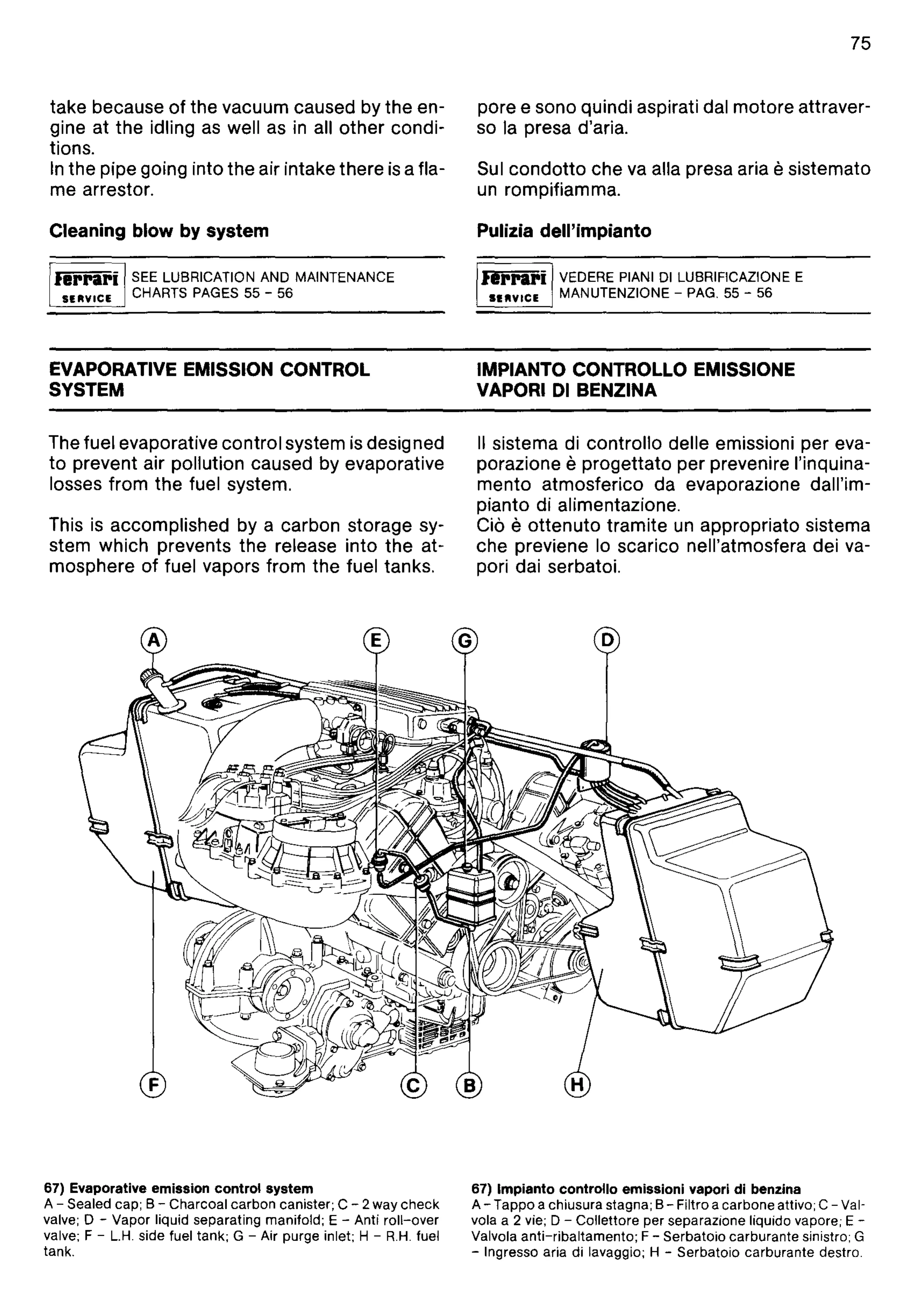
67) Evaporative emission
control
system
A - Sealed cap; B -
Charcoal
carbon
canister; C - 2
way
check
valve; 0 -
Vapor
liquid separating manifold; E - Anti
roll-over
valve; F -
L.H.
side fuel tank; G - Air purge inlet; H -
R.H.
fuel
tank.
67) Impianto
controllo
emissioni vapor; di benzina
A -
Tappo
a chiusura stagna; B- Filtro a
carbone
attivo; C - Val-
vola a 2 vie; 0 -
Colletlore
per
separazione Iiquido vapore; E -
Valvola
anti-ribaltamento;
F -
Serbatoio
carburante
sinistro; G
- Ingresso aria di lavaggio; H -
Serbatoio
carburante
destro.