73
Reqo!azione
,l
Iur,lnu
j\
!!!!!!O!'
K-Jetronic
A
~-~-~
~-~-~
~.
~
~~--,
~-~-~
I~
I
I~
I
.~
.-;.
'l
•
•
I
~
I
!
f~
i
i
l.-8.!!
i
l~l
i
I
•
I
i I
~l!
il~
j
•
~
t-
I
•
I
Wf
LH·'f-·ffJ
4-fH4,!
L
~--
·W
•
4l'f-W
4--T--W
._-
8181.80
....
pwO'
~r
ii
'"
•
.
~
m
...
....
~
"
....
~
~
~
•
1
~~
...
sa
0,8
•
•
a
T
••
•
•
rJi~'
•
•
.'• •
------
..- - -
---
0
•
r":
--_
..
_---
-
---
._-----
-
-,'
..
•
•
~
..
,
•
•
vavote fusiblll
U
C:
•.
•
•
•
Fuoes
W
in
&
~
. ,
"Oz
• • •
""J
iX-
N
SMO
O.
PIN
11
}-®
••
I
· ,
KI. 30
1-
.
PW
OL
08
PIN20
V
.•
:!
•
I
'0'
..
.
D~I
•
~
KI
15
I.;.j
"
z
BN
0,8 •
1-, .
SR02
KI.
MI
~
c..
1
~
•
J
..
I
Ii
1!
iz~".
....
n.
,
~!~+
®
PWOZ
l=fj
!'!i:M:
•
•
0
i
•
1
~
;
I
~
Ii f
l~
,
-,
f:'-
,
i"
r
-
r
r-
·
It-
f -
r
..,
r
,
• •
1
,..--
I
•
I
' i
I
• •
•
•
•
I
I .
•
O'
•
I
.
.1
•
I
I .
,
I
~!J
1
..
i
I I
M
--4}
I
I
I
,
•
i
•
•
i
L
il
•
•
\ L i
• •
1
J , ,
~
•
U
f-
'":1
CJ
•
L
l
•
•
1
• z
-~
•
--~
-0
._L
___
L
~
-
.L
H I L
0
P
a R
@
"-1'/
NC
!l1f33"c
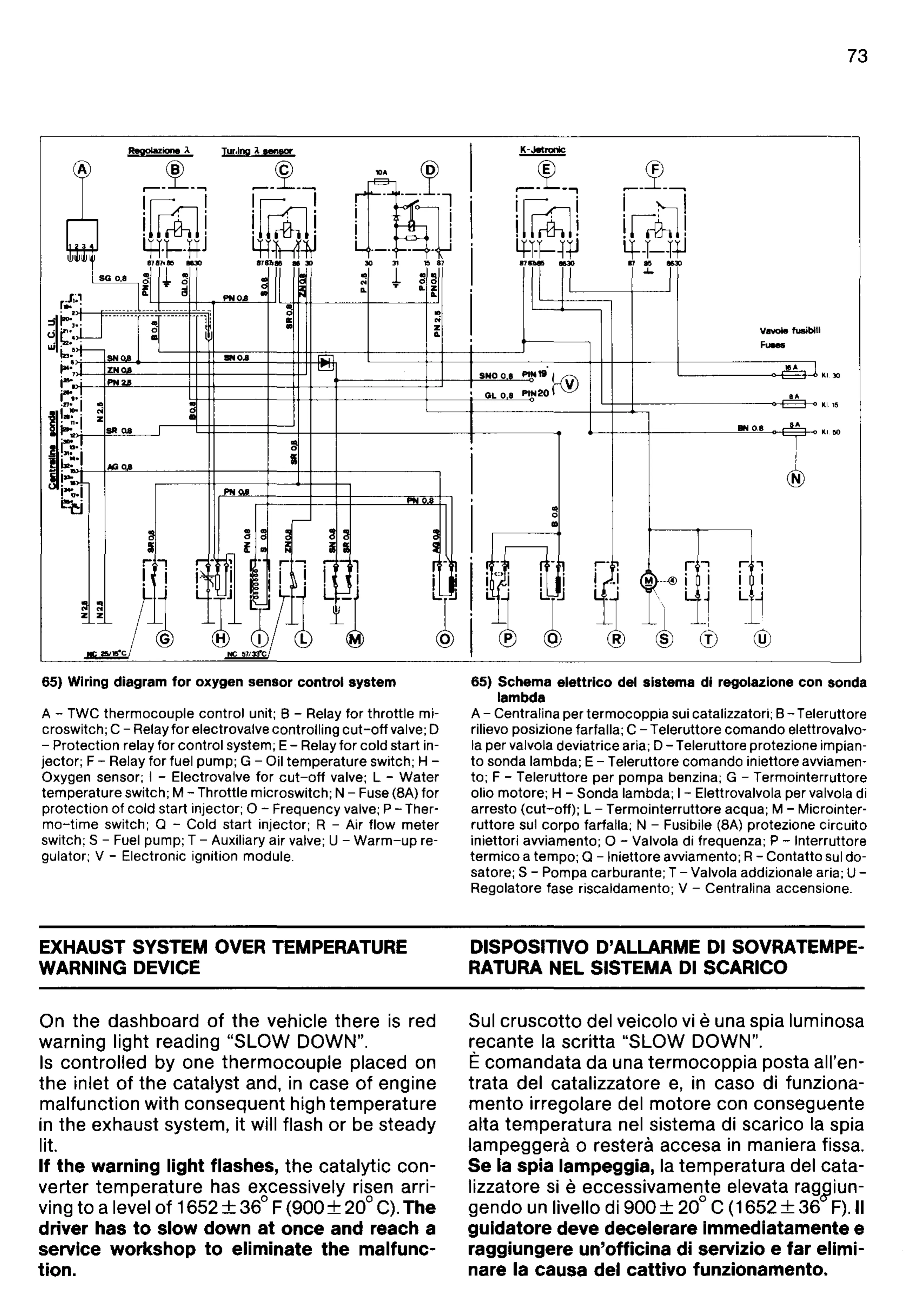
65) Wiring diagram
for
oxygen sensor control
system
A - TWC
thermocouple
control
unit; B - Relay
for
throttle
mi-
croswitch; C -
Relayfor
electrovalve controlling
cut-off
valve; D
-
Protection
relay for
control
system; E- Relay
for
cold
start
in-
jector;
F - Relay
for
fuel pump; G - Oil
temperature
switch; H -
Oxygen sensor; I - Electrovalve
for
cut-off
valve; L -
Water
temperature
switch; M - Throttle
microswitch;
N - Fuse (BA)
for
protection
of
cold
start injector; 0 - Frequency valve; P - Ther-
mo-time
switch; Q - Cold start injector; R - Air
flow
meter
switch; S - Fuel pump; T - Auxiliary air valve; U -
Warm-up
reo
gulator; V - Electronic ignition module.
EXHAUST SYSTEM OVER TEMPERATURE
WARNING DEVICE
On the dashboard
of
the
vehicle there
is
red
warning light reading "SLOW DOWN".
Is
controlled by one thermocouple placed on
the inlet
of
the catalyst and,
in
case
of
engine
malfunction with consequent high temperature
in
the exhaust system, it will flash
or
be steady
Iit.
If
the
warning
light
flashes, the catalytic con-
verter temperature has excessively risen arri-
ving to a level
of
1652+
36
0
F
(900+
20°
C).
The
driver
has
to
slow
down
at
once
and
reach a
service
workshop
to
eliminate
the
malfunc-
tion.
65) Schema
elettrico
del sistema di regolazione can sanda
lambda
A - Centralina per
termocoppia
sui catalizzatori; B- Teleruttore
rilievo posizione farfalla; C
- T
eleruttore
comando
elettrovalvo-
la per valvola deviatrice aria; D - Teleruttore protezione impian-
to
sanda lambda; E - Teleruttore
comando
iniettore
awiamen-
to;
F - Teleruttore
per
pompa
benzina; G - Termointerruttore
olio
motore;
H - Sanda lambda; I - Elettrovalvola per valvola di
arresto
(cut-off);
L -
Termointerruttore
acqua; M - Microinter-
ruttore
sui
corpo
farfalla; N - Fusibile (8A) protezione
circuito
iniettori
awiamento;
0 - Valvola di frequenza; P - Interruttore
termico
a tempo; Q - Iniettore
awiamento;
R -
Contatto
sui do-
satore; S - Pompa carburante; T - Valvola addizionale aria;
U-
Regolatore fase riscaldamento; V - Centralina accensione.
DISPOSITIVO
0'
ALLARME
01
SOVRATEMPE-
RATURA NEL SISTEMA
01
SCARICO
Sui
cruscotto
del veicolo
vi
euna spia luminosa
recante
la
scritta "SLOW DOWN".
-
E comandata
da
una
termocoppia
posta all'en-
trata del catalizzatore
e,
in
caso di funziona-
mento
irregolare del
motore
con conseguente
alta temperatura nel sistema di scarico
fa
spia
lampeggera
0 restera accesa
in
maniera fissa.
Se
la
spia
lampeggia, la temperatura del cata-
Iizzatore
si
eeccessivamente elevata
rag~iun
gendo un livello di 900+ 20° C (1652 +
36
F).II
guidatore
deve decelerare
immediatamente
e
raggiungere
un'officina
di
servizio e
far
elimi-
nare la causa
del
cattivo
funzionamento.