B Supplementary component overview
164 Festo – P.BE-MPA-EN – 1309f – English
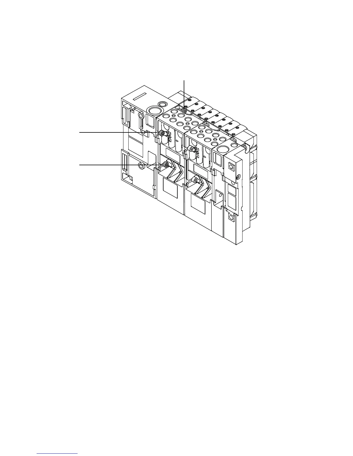
4. Insert the mounting screws in the corresponding holes. Tighten the screws in the se-
quence 1, 2, 3 ( Fig. B.4), at first slightly and then with 1.8 Nm (±10 %).
1
2
3
Fig. B.4 Mounting the MPA-S valve terminal to the port pattern
5. Fasten the M PA-S valve terminal to the mounting surface ( CPX system description).
6. Complete the electrical and pneumatic connections of the MPA-S valve terminal to the CPX terminal.
Further information can be found
– on the electrical connections in the CPX system description
– on the pneumatics in chapter 3 of this description.