5 Conversion and maintenance
120 Festo – P.BE-MPA-EN – 1309f – English
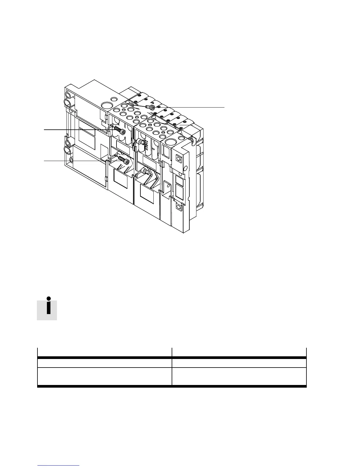
4. Screw the multi-pin plug connection plate to the pneumatic sub-bases. Tighten the screws in the
sequence 1, 2, 3 as shown in Fig. 5.15, in the sequence 1, 2, 3, first slightly and then with 1.8 Nm
(±10 %).
1
2
3
Fig. 5.16 Sub-base fittings
5. Mount the MPA-S valve terminal onto the mounting surface (wall mounting or H-rail mounting,
chapter 3).
6. Then install the pneumatic and electrical connections ( chapter 3).
5.4.2 Conversion of the MPA-S valve terminal to different pressure zones
Basic information on pressure zone separation can be found in chapter 2
( section 2.4.7).
The MPA-S valve terminal can be equipped with th e following number of pressure zones, depending on
the alternative electrical connection:
Alternative electrical connection
Number of pressure zones
MPA-S valve terminal with CPX terminal 1…8
1)
or 1 … 16
2)
MPA-S valve terminal with multi-pin plug connec-
tion
1…12
1) Electrical supply of the valves via the CPX terminal
2) Electrical supply of the valves via the electric supply plate
Tab. 5.7 Number of pressure zones
The pressure zones are formed either by special sub-bases or by special separating seals
( section 2.4.7).