2Overview
Festo – P.BE-MPA-E N – 1309f – English 37
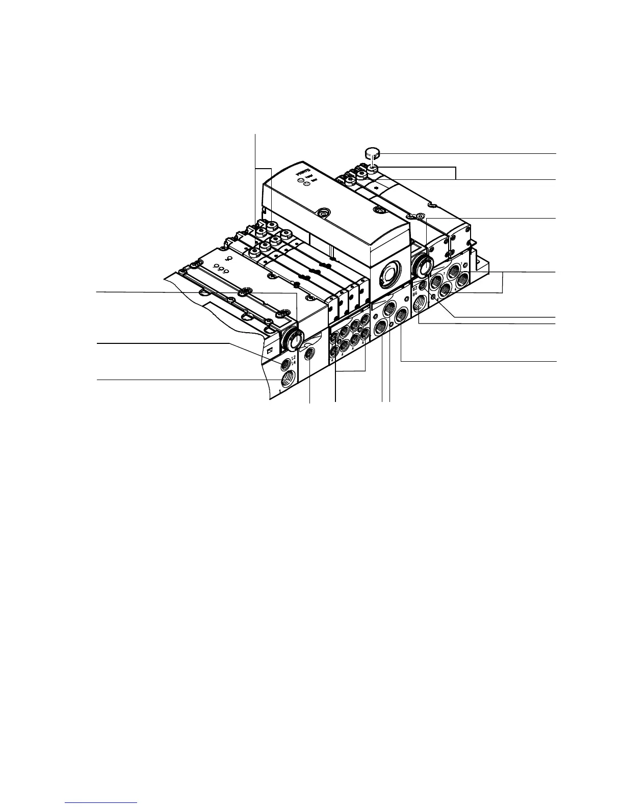
2.5 Operation and connection elements
You will find the following pneumatic connecting and control elements on the MP A-S v alve terminal:
1
2
3
4
5
6
7
8
9
aJ
aA
1
4
6
3
1 Manual override (per pilot solenoid coil,
non-detenting or turning with detent)
2 Manual override cover cap
3 Common exhaust por t ( 3/5), “Valves”
4 Working ports (2) and (4), per valve
5 Connection (82/84) only with variant for
ducted exhaust, “Pilot exhaust”
6 Supply port (1), “Operating pressure”
7 Pressure output (2) of the proportional
pressure regulator
8 Exhaust air (3) of the proportional pressure
regulator
9 Pressure input (1) of the proportional
pressure regulator
aJ
External pressure input of pressure sensor
type VMPA-FB-PS-P1
aA Pilot c onnection ( 12/14), “External pilot air
supply”
Fig. 2.14 Pneumatic c onnecting and operating elements of the M PA-S valve terminal