4 Commissioning
Festo – P.BE-MPA-E N – 1309f – English 95
4.5.2 MPA-S valve terminal with multi-pin plug connection or AS-interface
The LEDs on the valves show the switching status of the valve solenoid coils.
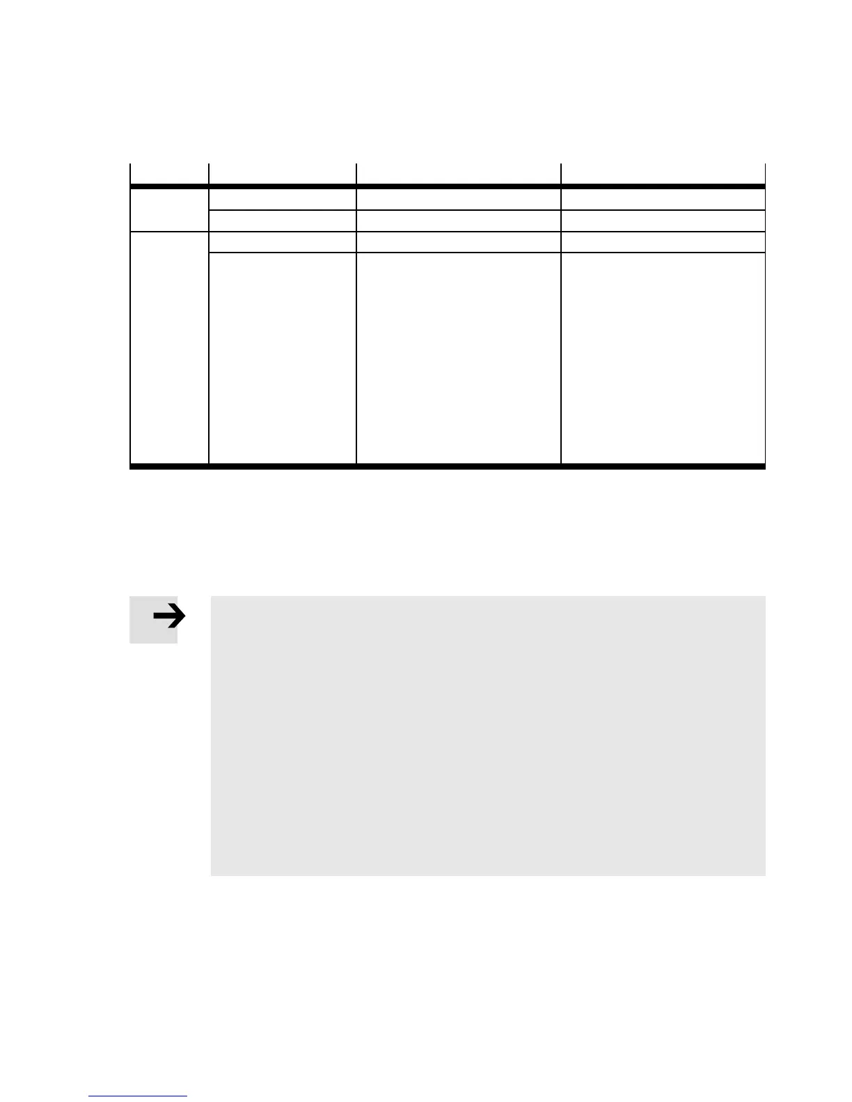
LED
Position of the valve Correct status Er ror status
Dark – Normal position Logic 0 (signal not present) —
– Activated — Logic 0 but MO actuated
Lights up
yellow
– Activated Logic 1 (signal is present) —
– Normal position — Logic 1 but:
–Operatingvoltageofthe
valves lies below the per-
mitted tolerance range
(18 V DC … 30 V DC)
– The compressed air supply
is not OK or
– The pilot exhaust is
blocked or
– Servicing required
Tab. 4.7 Significance of the LED display (MPA-S valve terminal with multi-pin plug connection or
AS-interface)
4.6 Commissioning instructions for the proportional pressure regulator
Note
• Make sure there is suffic ient space for the tube couplings. In this way you will pre-
vent the tubes from being bent.
• Make sure that high-frequency radiation (e.g. from radios, mobile telephones or
other interference-emitting devices) is kept away from the proportio nal pressure
regulator. In this way you will avoid increased tolerances in the out put pressure
(re fer to specifications on EMC in Appendix A).
• When switching off t he proportional pressure regulator, make sure that first the
supply pressure, then the supply voltage is switched off.
• Pressurize the proportional pressure regulator with an input pressure at least 1 bar
higher than the maximum desired output pressure. An output pressure P2 propor-
tionate to the setpoint value is then set. Tab. 4.8 shows the output pressure which is
assigned to the end ranges (1 % FS or 100 % FS) of the setpoint value.