3 Mounting and installation
62 Festo – P.BE-MPA-EN – 1309f – English
3.6 Connecting the MP A-S valve terminal
Connections on the following components are available for pneumatic supply to the valve terminal:
– on the electrical interface (pneumatic interface, CPI interface, multi-pin plug connection plate, AS in-
terface)
– on the optio nal pneumatic supply plate, ma ximum between ea ch sub-base.
3.6.1 Pilot control (pilot air supply)
Dependent on the variant of the pneumatic interface, CPI interface, multiple connector plate or AS in-
terface, the pilot control is supplied with internal or external pilot air. You can ascertain the pilot control
variant for which your MPA-S valve terminal is equipped by the following features ( Tab. 3.5).
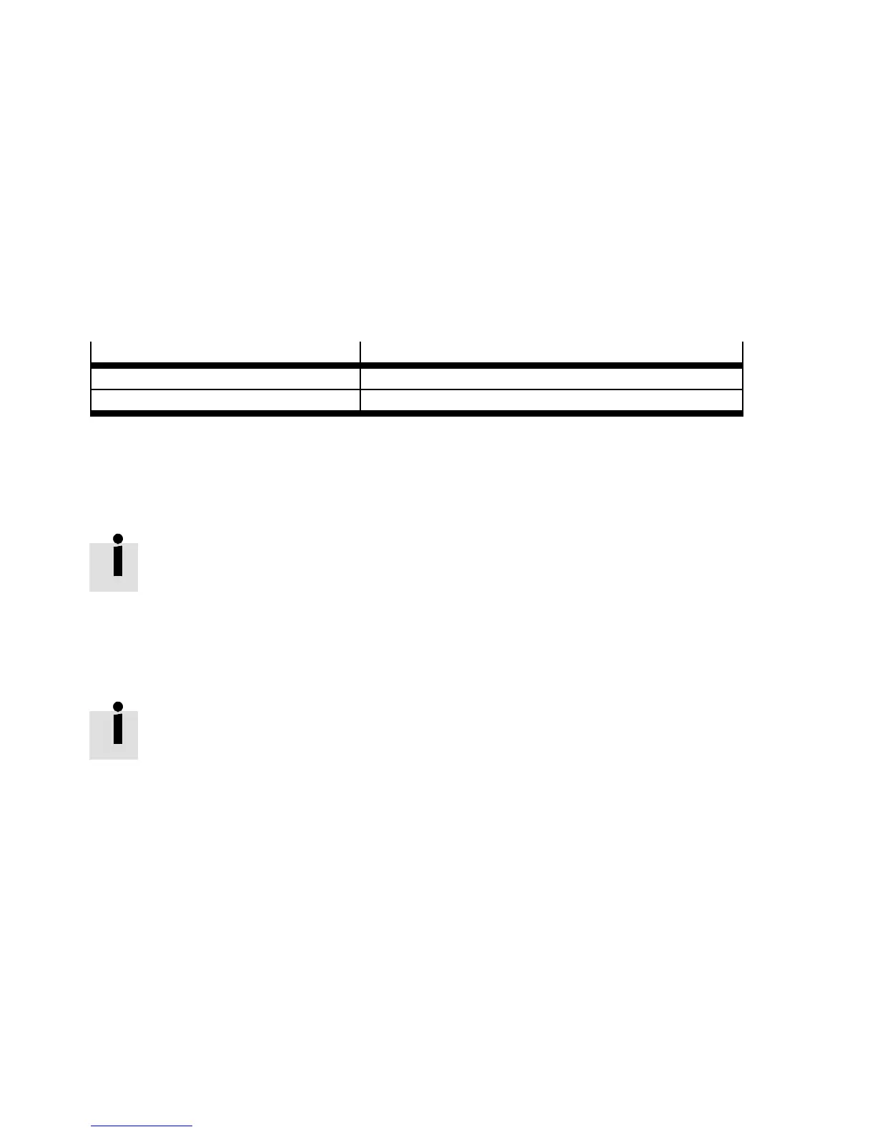
Pilot control variants
Pilot connection (12/14) on the electrical interface:
Operation with external pilot air marked and open
Operat io n with internal pilot air supply not marked and closed
Tab. 3.5 Recognition features of the pilot c ontrol variants
Internal pilot air supply
If t he operating pressure lies within the required pilot pressure range for the valves ( Appendix A,
Fig. A.1 … Fig. A.5), you can operate the pilot control with an internally branched pilot air supply.
The internal pilot air supply is branched centrally from the supply port (1) in the pneumat-
ic interface or multi-pin connection plate. This also applies when the MPA-S valve terminal
is operat ed with several pressure zones ( Fig. 3.6).
External pilot air su pply
If the operating pressure lies below the required pilot pressure or above 8 bar ( Appendix A,
Fig. A.1 … F ig. A.5 ), you must operate the pilot control with an external pilot air supply.
• Preferably use regulated external pilot air supply. Reliable, trouble free operation of
the MPA-S valve terminal is then possible, e.g. even with fluctuating operating pres-
sure.
• The external pilot air supply for all solenoid coils is fed centrally via the pilot port
(12/14) on the pneumatic interface or the multi-pin plug connection plate. This is the
case even if the MPA-S valve terminal is operated with diffe rent pressure zones.
• Adapt the external pilot air supply to the operating pre ssure at which these valves are
operated ( diagrams in Appendix A, Fig. A.1 … Fig. A.5).
Conversion between internal and exte r nal pilot air supply is described in section 5.4.1.